Thermal Pastes (heatsink paste for CPU's) is NOT to be used, it's not electrically conductive.
Aluminium Paste has its place but NOT with batteries like this.
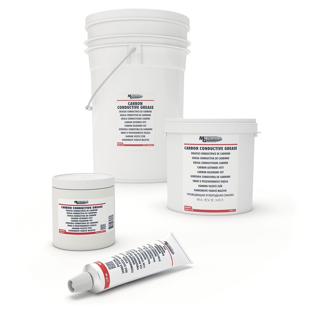
These two products below are highly recommended.
* Application Tips:
- Do not put on Threads of screws/bolts as this acts like a Grease and will affect torque readings.
- Use only a very minimal amount between cell terminal face & busbar. Just a light wipe on both contact faces is all that is needed.
No-Alox https://www.idealind.com/ca/en/shop/noalox.html or
OxGuard
Ox-Gard Anti-Oxidant Compound contains prime grade zinc and is formulated with metallic zinc to create a compound that enhances electrical and thermal conductivity which is used on high power crimp connections and stud bolt mountings. When the connection is tightened, the grease is displaced...

www.gardnerbender.com
BTW: I use Active Balancers on all of my packs.
<--- QNBBM 8S Active Balancer. (All production packs)
I route the BMS Harness Wires to the Common Block on the QNBBM Balancers then 14Ga wire to Cell Terminal.
*NB: Production Packs use Chargery BMS8T-300's with 300A DCC's.
** Passive Balancing ON only during Charge over 3.300V and to 30mv differential.
this helps prevent runners and assists Active Balancer when at the top of charge cycle.
Hope it helps, Good Luck.
Steve_S
View attachment 60624
<---- Molex 9-Port for 8S BMS/Balance leads,
With the HelTec Active Balancers (Utility packs) I'm doing similar but BMS Harness & Balancer goto a 9-Port Molex Connector and then to Cells with 14Ga wire.
*NB, Utility Packs also use JBD Smart BMS' PN: JBD-SP08S004


 . So to be sure, I will order an other paste. Any suggestions? Dumb question: could you also use the same pastes like when installing a CPU to the socket?