diy solar

diy solar

16S LiFePO4 Battery Build / Critical Circuit Off Grid Inverter Install

Burke

New Member
Joined
Nov 17, 2020
Messages
98
After about 9 weeks (bought them during the worst part of the year), I finally received the 20 Lishen 272 Ah cells earlier this week.

Very well packaged, two per box. I bought 20 just in case there was a bad cell, and I hope to build the 4 extra into a 12V pack if all are fine which is what I am expecting. Shipped 2 per box I believe to be under the maximum weight for FedEx delivery once offloaded from the container ship.

1 Batteries in Boxes.jpg

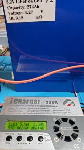
I wanted to test the capacity of these new "Grade A" cells. They certainly do look new, no dents or dings, clean terminals. I am using my trusted iCharger 208B which has been extremely reliable over the years, I do like it a lot. Feeding it with a 28V/25 Amp CCTV Power supply for charging.
I made up some beefy charge leads and charged Cell 1 to 3.6 Volts. My charger measures internal resistance of 29 mOhms vs the label of 0.12, but will check that soon with a known accurate meter and a resistor to confirm.
4 Discharge Leads.jpg0 Internal Resistance.jpg

Charged it to full capacity at 3.6 V at a leisurely 10 Amps. It is amazing how this cell just sucks the juice like a black hole.

3 Charge at 10 amps START.jpg

After 26 hours and 43 minutes the battery was fully charged, added 232 Ah to the battery. This stopped some time overnight and the cell voltage settled to 3.4 V.

3.1 Charge Finished 232 Amp Hours.jpg

Capacity Test. I discharged the cell at 15 Amps, but I think there is another setting I missed and it self limited to 20 Watts or 6 Amps at the cell voltage.
Confirmed the Amp discharge rate with my Fluke, right on the money.

7 Discharge at 6 amps 12 hours in.jpg6 Discharge Amps Matches Charger.jpg

It is a big cell, took 45 hours to discharge at only a 6A rate, but total capacity is 280 Ah, a bit more than the rating of 272 Ah, nice!

9 Discharge Done.jpg

So after some math, I can calculate the SOC from the factory. I am going to recharge cell #1 here to 48 Ah so it is in the same state as the other batteries. I will parallel them till the cells normalize, then use the iCharger to balance charge the cells as two separate 8S packs to top charge them. I made up an 8S balance connector for the charger, it is going to take a while even at the max 20A - but they should be very closely matched for capacity.

1610853778990.png

So far the cells are impressive. I will document the build of the battery and the installation here as I progress. This will be used as a critical circuit home UPS, using a Growatt 6kw, split phase low frequency inverter. I plan on adding solar panels when I can.
 

Attachments

  • 5 Discharge Start.jpg
    5 Discharge Start.jpg
    104.1 KB · Views: 21
Last edited:
Here is the installation so far for the house UPS. Not fully wired yet, but there is a two pole generator transfer switch installed. This will be fed by either the main panel (40 Amp two pole breaker) or a generator fed via plug installed outside. This will feed the Growatt utility or generator power which will charge the battery and feed the critical circuit panel.

I still have to relocate circuits out of the main panel, and a couple from the existing sub panel. I am waiting for some weekend weather that isn't 25 F or colder, and not raining, to install the inverter disconnect switch outside the house. This disconnect is for the AC Inverter output, goes through a 2 pole disconnector on the outside of the house so emergency response personnel can kill the panel from the outside assuring there are no live AC circuits in the house. I won't tie in the feeds to the main panel until everything else is done. A bunch of wiring cleanup still needs to happen

cropped 20210102_201522.jpg20210105_213834.jpg
 
Last edited:
Inside of the Inverter, those spaghetti cables.... Yikes... Not the worst I have seen though. Clearly a lot of components fit together vs a custom designed unit. Can't complain based on the cost if it performs well. Solid bus bar power carriers from the battery connectors to the boards. Everything was tightly torqued and secured to prevent flapping in the wind, Silastic silicone adhesive on all of the board connectors so they don't pop out, with marks on all of the connectors implying they were all checked by someone.

20210105_153807.jpg
 
Last edited:
I noticed the table was missing the SOC for the as received condition. Seems like there is a time limit on edits to posts?

1610984432653.png
 
Very similar setup to what my build is.. ?. No generator for me.. I will be using main panel for charging when solar/batteries are too low.
Good luck with the build! View attachment 33883
Nice. I will be using utility primarily, the generator is for when the power goes out, will supply the panel and recharge the batteries.
 
After a few days of parallel charging all 16 cells i configured 8 into an 8S pack
Added the balance leads and started to balance charge. My charger has a 350 watt limit. I may get a charger with more capacity. 24V hacked server power supply (65 A at 24V)

20210122_210032.jpg
20210122_210037.jpg
 
After taking a long time to get bank A top balanced, I decided to speed things up and ordered an ISDT P30 charger. I have a couple of ISDT itms (a cell charger AA,AAA,18650) and a balancer (for LIPO packs) and they are definitely a cut above. My 208B has been and still is awesome, but the 350 W charging limitation met it's match with these large cells.

I had all 16 cells on parallel charging at 3.6 V for about 5 days. Voltages were just starting to get into the 3.35-3.45 territory when I stopped and put the first bank (bank A) into an 8S configuration. Balance charging at 350W, and a 3.6V cutoff one cell peaked out after a couple of hours. Most of the other cells were still in the 3.3-3.5 range so I individually charged each of the lower cells to 3.6 volts then put it back on the balance charger. Individually each of the cells absorbed from 1 to 3.8 Amp Hours, so they were still a little bit off from each other. After doing this two times the cell voltages were much closer, within 0.060 volts. I let the 208B finish a balance charge which didn't take that long,

As luck would have it the P30 arrived just as the balancing finished. After making up a charging input adapter cable and new charge leads I plugged it into Bank A and tried out the new 750W charger in balance mode. Nice, went right up to 27A (750 Watts) and stayed there for 5 minutes (it was already topped off and balanced) until the first cell hit 3.61, then went into balancing mode. The P30 balances at 1.5 Amps, much faster than the 208B. In about 10 minutes it had all cells at 3.6V. while the 208B got everything to within 0.03V - not that it matters all that much I suppose. :)

I have it now Balance Charging Bank B, cranking along, we will see how long it takes to top off bank B, but I am really liking the charger.

ISDT 27AMP.jpgISDT BANK B.jpg
 
Last edited:
Could you link the bms that you are using? What do you think of the growatt? I'm looking to get the 6k version of this model Just ordered 16 272 cells today for 48v system build. Intent is to run a sub panel and leave stove and ac, hot water on main panel. my night consumption is between 300-550 watts an hour so the thought is to be net 0 day and night cept for big appliances.
 
Could you link the bms that you are using? What do you think of the growatt? I'm looking to get the 6k version of this model Just ordered 16 272 cells today for 48v system build. Intent is to run a sub panel and leave stove and ac, hot water on main panel. my night consumption is between 300-550 watts an hour so the thought is to be net 0 day and night cept for big appliances.
I amusing the Daly 300 Amp, 48V LiFePO4 BMS -

I haven't powered up the system yet, but the Growatt seems fairly well built. All connections inside were tight, and had silastic on the connectors to prevent disconnects. It can handle a very large surge due to the large transformers, and I would expect it to handle motor starts easily.

I am working on the battery box, using 8020 extrusion and waiting for it to arrive so I can buildup the pack. Once the pack is built, I will install the external AC disconnect which is required in most localities so emergency responders can kill all AC circuits in the house from the outside.; Then the final step would be to move circuits out of the main and existing sub-panel into the critical circuits panel. I will post some more details soon of the wiring plans.
 
Last edited:
Still waiting for pieces parts to arrive but here are some of the other components I do have.

2P Main Battery Disconnect (also a 200 Amp breaker) will be between bus bar and Inverter. A 1P version will also be used in the battery as a battery disconnect and overload protection. It is extremely robust. And freaking huge! This will be in a box and I will also integrate a pre-charge circuit into the same box. I will take a picture of the internals and post if anyone is interested.

2P Disconnect 1.jpg

2P Disconnect 2.jpg

Anderson Connector (350) for connecting the Battery to the Bus Bar. The output battery connector will be affixed to the battery box. Blue is for 48V systems if you want to play along with the standards as far as I can tell...

Anderson Connector.jpg

I was looking at making a bus bar, but the Victron Power In is a really nice unit for the money, so I decided to get one. Will support two Battery Banks if I ever decide to add another battery.

BusBar.jpg
 
I have been waiting for the materials to build the battery box, in the meantime today I installed 1/8 neoprene foam rubber pads (60 durometer) between the cells on two banks. Just the right squishy/firm ratio in my opinion :) They are just the right size (1/8") to allow the bus bars to fit at the long end of the slotted holes. The foam will provide additional separation, and will prevent cell to cell contact once I install them in the box and add some compression. Bought the foam on ebay, 54" x 12" and cut them down to 7.75" x 6" for the cell pads.

20210215_145220.jpg

20210215_150244.jpg

I took each cell from the pack one at a time and put the pad on the right side so there is on on each cell.


20210215_151256.jpg

I cleaned off the cell wrapper with Isopropyl and a paper towel before applying the pads. I eyeballed placement.

20210215_151315.jpg


20210215_151632.jpg
Installed back into the 8 cell bank. The pads will also be between the compression plates and the cells on the ends of the cell bank.
 
Almost finished the Battery Disconnect box:

200 Amp DC 2P Breaker / Disconnector - feeds the inverter

Precharge Circuit with Volt/Amp Meter - The meter will indicate voltage of the Inverter caps so you know when it is fully charged.

12Volt Sub System - I needed 12V to power the meters, so I installed a step down unit to provide 12V to the meters, and also gives me power taps directly from the battery if I ever need them. USB Rapid Charge ports (2), and 2 10 amp adapters, all independently fused using the 6 circuit fuse block. The top meter will show the battery voltage, and the amps being drawn by the 12V sub-system (at 48V).


Disconnect Box Open 1.jpg


Disconnect Box Operating.jpg


Disconnect Box USP 3.0 Charging Ports.jpg
Disconnect Box 12v Outputs.jpg
 
Last edited:
Almost finished the Battery Disconnect box:

200 Amp DC 2P Breaker / Disconnector - feeds the inverter

Precharge Circuit with Volt/Amp Meter - The meter will indicate voltage of the Inverter caps so you know when it is fully charged.

12Volt Sub System - I needed 12V to power the meters, so I installed a step down unit to provide 12V to the meters, and also gives me power taps directly from the battery if I ever need them. USB Rapid Charge ports (2), and 2 10 amp adapters, all independently fused using the 6 circuit fuse block. The top meter will show the battery voltage, and the amps being drawn by the 12V sub-system (at 48V).


View attachment 38962


View attachment 38963


View attachment 38964
View attachment 38965
That is a great build!! Nice job.
 
How much did the growatt inverter cost? and will it do 220? The set up i have envisioned for myself is a lot like yours but wasnt sure if i should do 2

3k units, with 20 panels split into 2 main strings.​

 
Back
Top