It was just under $1300, and it ouputs two phase 110v so you can do 240 for pumps and welders and such.How much did the growatt inverter cost? and will it do 220? The set up i have envisioned for myself is a lot like yours but wasnt sure if i should do 2
3k units, with 20 panels split into 2 main strings.
You are using an out of date browser. It may not display this or other websites correctly.
You should upgrade or use an alternative browser.
You should upgrade or use an alternative browser.
16S LiFePO4 Battery Build / Critical Circuit Off Grid Inverter Install
- Thread starter Burke
- Start date
I still haven't received any update on my battery order, how do i go about seeing where they are at on the order and shipment?
I was going to get 2 stack able 3k growatts but they are high output, i think it might be better to get one like your model and have the option to run say my water heater or lower wattage more intense machine. but that would lock me into the 6k models, all i can afford. Although if this goes as planed in a coupple years this might migrate to me sons house and i might have to upgrade mine a little, time will tell. What andvantages would i get if i were to use like a midnight solar charger and the growatt. I see people doing that and dont get it , if the growatts are all in one why do it with a external charger?
I was going to get 2 stack able 3k growatts but they are high output, i think it might be better to get one like your model and have the option to run say my water heater or lower wattage more intense machine. but that would lock me into the 6k models, all i can afford. Although if this goes as planed in a coupple years this might migrate to me sons house and i might have to upgrade mine a little, time will tell. What andvantages would i get if i were to use like a midnight solar charger and the growatt. I see people doing that and dont get it , if the growatts are all in one why do it with a external charger?
I wanted to have the two phase output in case I needed to run my irrigation well for water in an emergency (240). And it makes the installation easier, I am just wiring the two phases into a sub-panel so if I need a 240 line, I can just add the breaker and wire in easily. Even though they are less efficient, I like the low frequency inverters as they have less issue with starting motors as they have lots of inductance due to the coils. I like the all in one types of hybrid inverters, some might say it puts all of your eggs into one basket, but if I ever wanted to add a separate charge controller I can just add it independently. For now Solar Panels are a free option in the future. Once it is in place, I will have an uninterruptable power supply for all of my critical house circuits and I can use a generator to keep the batteries charged in a long term power outage.
The batteries will be a mystery until they are collected at the port for transportation to your location. Can be frustrating, but be patient!
The batteries will be a mystery until they are collected at the port for transportation to your location. Can be frustrating, but be patient!
Yes. if there is grid power, it will bypass that to the panel. But if the grid power goes down, it will switch to battery, like a UPS. That is how I will be using mine. Or if you have solar panels, you can prioritize to use solar first, then supplement with grid power to make up the load.Will the growatts still run if in off grid grid assist mode? So as to have the sub panel powered 24/7 if solar and battery s are good to go ? Or will one still need say a pure sine inverter to kick it on and run just sub panel?
No worries.Sorry about asking on battery's I confused that with another post.
D
Deleted member 1888
Guest
Anyone have a link to that breaker? If you also know of a 300a DC beaker I can use that too.
Anyone have a link to that breaker? If you also know of a 300a DC beaker I can use that too.

36.0US $ 20% OFF|Dc12v Dc24v Mccb Circuit Breaker 150a 200a 250a 300amp Rated Current For Batter Car Charger New Enery Power Protector Automatic - Circuit Breakers - AliExpress
Smarter Shopping, Better Living! Aliexpress.com
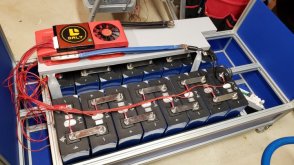
Have been waiting (and buying) the parts of the battery box as time and money permits. I have built numerous items with 8020 extrusion for work so I wanted to do something similar for the battery box.
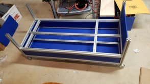
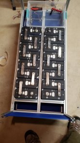
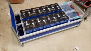
The base of the box, using 1" extrusion. Two banks divided in the box. There are castors on the box to wheel it around.
3/16 Neoprene Rubber Strips to stop the cells from moving, and to provide some dampening.
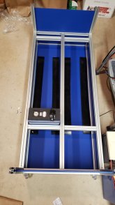
Bank B Transferred into the Box

Bank A and B in the box...
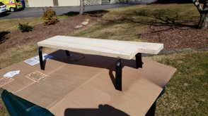
BMS Shelf, sits in the extrusion channels. 5/8" Plywood, and the legs were made from some old wire shelf supports. Hammered them flat and into the right shape. Painted them, and I am trying something new. I sprayed the whole shelf with that spray seal stuff I had lying around. Mostly to make everything non conductive. but also to make it look better. We will see... In fact all of these parts were stuff I had left over or haven't gotten around to throwing them out yet. This concept is very difficult to explain to my wife who can't understand why I keep some things.
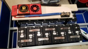
Once I get everything wired (BMS, 200 Amp Disconnect (1P), Anderson Plug, etc) I will add the top of the box frame, and the lid. The lid will hinge from the back and open like a toy box.
I am also going to use a Chargery 16S BMS as a battery monitor so I can see what is happening with the individual cells.
The base of the box, using 1" extrusion. Two banks divided in the box. There are castors on the box to wheel it around.

3/16 Neoprene Rubber Strips to stop the cells from moving, and to provide some dampening.

Bank B Transferred into the Box

Bank A and B in the box...


BMS Shelf, sits in the extrusion channels. 5/8" Plywood, and the legs were made from some old wire shelf supports. Hammered them flat and into the right shape. Painted them, and I am trying something new. I sprayed the whole shelf with that spray seal stuff I had lying around. Mostly to make everything non conductive. but also to make it look better. We will see... In fact all of these parts were stuff I had left over or haven't gotten around to throwing them out yet. This concept is very difficult to explain to my wife who can't understand why I keep some things.


Once I get everything wired (BMS, 200 Amp Disconnect (1P), Anderson Plug, etc) I will add the top of the box frame, and the lid. The lid will hinge from the back and open like a toy box.
I am also going to use a Chargery 16S BMS as a battery monitor so I can see what is happening with the individual cells.
Last edited:
Got the bms shelf done. I also extended all of the leads of the balancing harness by 18" as they were too short for where I am putting the BMS and installed ring terminals. Hooked everything up and jumpered the B- to the Battery terminal and I get 53 Volts from the Battery + terminal to the P- connector on the BMS so it is working!

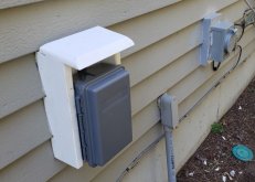
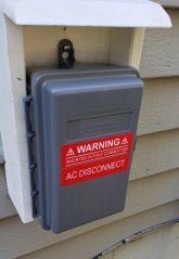
The weather has been nice finally this last week so I was able to get the external AC Disconnect installed. Built a semi-enclosure for it to mount it on the clapboard siding properly, made from 3/4" PVC Sheeting. Made a similar one for the Generator plug as well. Now the Inverter is wired through the disconnect and through to feed the panel! Getting close, now just need to finish the battery, and do the DC cabling for a power up test. Once everything is working properly, I will move the critical circuits from the other two panels and tie the inverter into the grid.


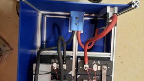
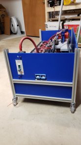
I am using the chargery 16s bms as a monitor and alarm system only. Installed it yesterday, configured and seems to work fine. The shunt is for the Chargery. I really just wanted a way to monitor by cell level and overall battery health. For $110 this is a good way to provide details into battery state. Screen will be mounted outside the box on the lid. Also got the Anderson plug mounted. Just need to add the 200 Amp breaker/Disconnector (rectangular hole, waiting for some long screws, and the rest of the 0/2 wiring and then it is adding the rest of the side panels, and the lid.
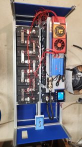
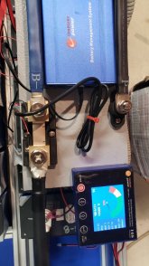


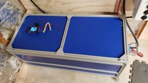
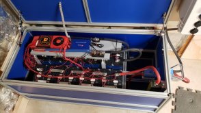
Well, got the battery completely finished, and all wiring done.
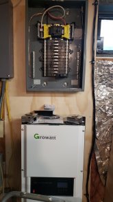
Today I did the first power up of the system and did testing. Seems to work well, although I need to check on some settings for the Growatt ralated to the battery charging settings. I had a problem with the first turn on as I had checked and rechecked everything numerous times. No AC input or output. Well after about 10 minutes of troubleshooting I realized I never turned on the AC Input and output breakers on the inverter! DOH!
Once I sorted it out, everything works really well. Precharge circuit worked well, I am glad I added that in. A shut down of grid power instantly converts to the battery. I have one circuit installed in the new sub-panel so far (the power feed for the house networking stuff which is just to the left and part of the service entrance. The inverter fans are pretty loud even when doing AC Pass through, and gets louder when under load. In my case it is in my basement so won't really bother anyone, but it was louder than I expected.
I still have some things to do, like more cable management, relocate some existing 110 plugs, and of course move all of the critical circuits from the other two panels into the new sub-panel. I also have to relocate the battery box disconnect in the battery box as the cable sticks out higher than I expected and it prevents the top door from closing all the way. But really happy with it, lots of work to get here, but I like the way everything turned out.
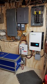
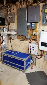


Looks great, nice job.
I made a lot less nice version, but similarly 16s 310(advertised) Daly 100a Smart bms into an eco worthy 3500 hybrid. My goal was to essentially replace my predator 3500 inverter generator and it basically has. Its sitting on my shop bench now but will eventually be on a landscape cart with inverter mounted to the back to be somewhat portable. I have no 220 devices in my house so 110 is fine. A custom l5-15p to l14-30 adapter lets me hit both sides of my panel. I don't have a shunt but I did a pseudo capacity test the other day. I plugged in a heater with a constant 12.4a ac draw, which came out to 31a dc @ 48v coming out my batteries, plugged in a 110v clock, set it to 12 and sent it. When the system shut down due to low voltage the clock also stopped letting me know how long it ran for. It ran for 9hr 10m drawing 31a per hour. Rough math gave a 285ah estimate. I spent a lot of time on my app and charger settings making sure the high voltage charge setting were right but I didn't do anything on the discharge side, so there may have been more energy to spare but this was a good first test.
I do have a much smaller bms than you but it looks as though your balance leads came with a reasonable amount of wire. I have mine in a 2/8 pattern as well with no foam so the entire pack is smaller but my wires are still ridiculously short. So short my bms is on a rubber mat atop the cells because it cant go to either side. I think I'll try to find your balance lead for my smaller bms.
Again nice job.
Upgrading the BMS as the Balancing and Power out for the Screen failed on the BMS, but other functions seem to still be working.
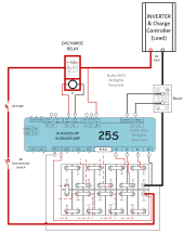
Moving to the JK-B2A25S-RP balancer which uses relays to switch power. Once I get the new one in I will open up the old one and see if I can determine what happened. After looking for reference material, this is the wiring diagram I came up with in case anyone else needs a reference. If it is wrong, I will come back and update. . This unit also has relay outputs for a charge controller and a precharge circuit. I am just using a discharge relay at this point.
Wiring
Moving to the JK-B2A25S-RP balancer which uses relays to switch power. Once I get the new one in I will open up the old one and see if I can determine what happened. After looking for reference material, this is the wiring diagram I came up with in case anyone else needs a reference. If it is wrong, I will come back and update.

Wiring
Similar threads
- Replies
- 11
- Views
- 314
- Replies
- 12
- Views
- 627


