• Have you tried out dark mode?! Scroll to the bottom of any page to find a sun or moon icon to turn dark mode on or off!

diy solar

diy solar

192V/60S

Mentalis

New Member
Joined
Oct 30, 2021
Messages
7
Thank you @Will Prowse for the forum.

I have a 208V inverter from APC, SURT10000XLT. The DC input voltage is 192V, and have 2x APC SURT003 giving 120, 208, and 240 output from the inverter. I'm looking to build a battery pack and I see lots of options, so far I've settled on purchasing 16x (for now) of the Zooms/Chins battery packs. It seems the cell quality is good, they each come with a BMS, but I see the packs I linked as manufactured come with a 48V limit. Obviously this is a limitation of the BMS (true?), but for the price it seems good for the cells.

Really I'm just here for hardware suggestions.
This will never be grid tie, but it's pretty high voltage so I'd like some second-hand experience before I get more involved or do something uneducated.

I plan to run my well (1HP) and pool pump(0.5HP), the pool water will be lightly pressurized against the back of the PV panels using some soft PVC.
I also have a 208v-25amp multi-zone split system for A/C and some 1200-2400w 120v temp controlled in-line water heaters.

Could anyone offer some BMS recommendations (EV based?), PV charging approach, alternate cell recommendations?

Thanks in advance.

EDIT (minutes later):
I've found these 280AH 3.2V cells with studs from watching one of Will's videos. For 60S, can I set up 4 banks of 48V with some high-amperage BMS and be "okay"? It seems the max current would be ~75A, but what limits the circuit voltage with these batteries?
 
Last edited:
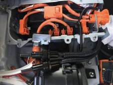
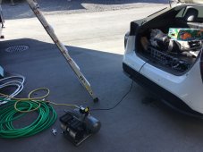
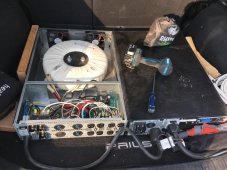
I have a SURT5000XLT and a SURT6000XLT (the 6000 is installed in the trunk of my 2018 Prius, used as a power source / generator (along with the SURT003 transformer)...

I have looked into this as well a bit, on how I could hook up more batteries if desired. The best option I have come up with is most likely this BMS:


Supports up to 255 cells if you buy more modules. I thought I had figured I needed 56 cells of LiFeO4 for this... I was even thinking of adding LiFePO4 cells to the car to add EV capacity (since Prius hybrid has an EV-only button on the dash)...

I have bigger fish to fry for now, since I have a set of MPP LV6548 inverters to use on my off-grid house project, so this stuff I have now with the APC in the car as a power source is fine as it is for me, and I already use the car a lot as a generator only to give me power when I'm out working at the storage unit or on the property, so I doubt I will get back to trying out the 123 Smart BMS, but you never know, we'll see...


1635794972411.jpeg

1635794938925.jpeg

1635795111260.jpeg
 
Last edited:
BTW, on the SURT6000XLT (and 5000), you can change the output voltage on the inverter unit up to 240v in the settings on the SSH/Telnet CLI menu (access via IP over the onboard LAN module and Ethernet), and there is a physical switch you set to 240v input on the SURT003 if you want to use standard AC voltage for US... My guess is the SURT10000XLT would allow to change it to 240v too?

You have to change it in both places, the inverter via CLI menu, and on the transformer input physical switch...
 
Last edited:
EDIT (minutes later):
I've found these 280AH 3.2V cells with studs from watching one of Will's videos. For 60S, can I set up 4 banks of 48V with some high-amperage BMS and be "okay"? It seems the max current would be ~75A, but what limits the circuit voltage with these batteries?

Also BTW, 75a is a lot considering the high voltage DC, remember as the volts goes up, the amps goes down. On my Prius, I calculated around 25a of draw, so I put 30a fuses on my DC wire (first picture above) connecting to the Prius battery and I've never blown them. If I try to start my big 4 hp 14.5a 240v air compressor it trips my inverter first.

I considered trying a SURT10000XLT to see if it would start that thing. I even tried putting a soft-starter on the compressor and it tries to turn it now but still trips the SURT6000XLT after about 5 seconds in... It runs my chop saw, drill press, miter saw and small compressor fine though.

I would guess your SURT10000XLT would only draw up to 50 or so amps off the DC bus. You could test it with an amp-clamp probe to be sure...
 
Last edited:
Very interesting seeing the inside of the SURT003.. I expected it, but dang that's a huuuge coil. Well, I wasn't able to buy batteries. Lol, I could maybe get 192v using 18650s right now.

I will go for your SmartBMS suggestion, if you have anything else please let me know :)
 
Very interesting seeing the inside of the SURT003.. I expected it, but dang that's a huuuge coil. Well, I wasn't able to buy batteries. Lol, I could maybe get 192v using 18650s right now.

I will go for your SmartBMS suggestion, if you have anything else please let me know :)

Yeah that SURT003 is heeeeeavy!
 
I have still not purchased batteries for this UPS, I still intend to use it as an off-grid inverter. I believe the battery input voltage is 192v at the board. Still have not planned any further. Does anyone have experience with the 10kv model?
 
You cannot hook several standard 48v bms’s up in series - I believe the FET’s in them will be fried at the higher volts.

I use a Batrium bms on my MotorHome (I wanted a high amp solution), but it can be used with high voltage.

I have been thinking about a 96v battery or a 144v battery (for an electric powered boat) and that is the bms I would use on it. My thoughts are for each 48v pack have a Tyco EV200AANA contactor (Relay) break the interconnect wire between the packs - that way with a switch I am back to 2 or 3 48v batteries for maintenance.

The bms would be the Watchmon core and then a Cellmate K9 for every 16s segment (48v).

Anyway Good Luck with your project.
Be safe around the high DC voltage.
 
Sorry, I may have been mistaken. The SURT10000XLT from APC apparently takes two 192v lines in series for 384v? Could it be +192, 0, -192?Batteries for this UPC are always sold in pairs and I never had access to original packs to inspect. If anyone knows, count me Lost and trying not to cause failures. I would certainly like to avoid use of a BMS and find another way to manage cells if possible. I need to study more.

Will certainly be wearing dry leather around anything I do with this project.
I'm 100% sure I have no idea what I'm doing and would be thankful to work with some folks who do.
 
Last edited:
Sorry, I may have been mistaken. The SURT10000XLT from APC apparently takes two 192v lines in series for 384v? Could it be +192, 0, -192?Batteries for this UPC are always sold in pairs and I never had access to original packs to inspect. If anyone knows, count me Lost and trying not to cause failures. I would certainly like to avoid use of a BMS and find another way to manage cells if possible. I need to study more.

Will certainly be wearing dry leather around anything I do with this project.
I'm 100% sure I have no idea what I'm doing and would be thankful to work with some folks who do.

Yeah, the SURT10000XLT input is 384v nominal...
 
I still have this thing sitting around and I have no idea which angle to approach it from. I do know it is 192v as the battery banks are supposed to be hot-swappable. The surt10000xlt is apparently just a beast industrial unit that I probably should never have accepted, it and its two companions are so heavy, but I could go for a working, reclaimed setup. This unit was bound for the recycle machine, and worked, but the past owner upgraded to the big-bux lithium setup instead of going for new lead-acid.
 
Last edited:
I still have this thing sitting around and I have no idea which angle to approach it from. I do know it is 192v as the battery banks are supposed to be hot-swappable. The surt10000xlt is apparently just a beast industrial unit that I probably should never have accepted, it and its two companions are so heavy, but I could go for a working, reclaimed setup. This unit was bound for the recycle machine, and worked, but the past owner upgraded to the big-bux lithium setup instead of going for new lead-acid.

I wouldn't assume it is 192v, the batteries would of course be hot-swappable if on grid mode anyways. You may want to pull the cover and confirm with a volt meter the main battery (charger) voltage, or test it some known common point (like the Anderson connector made for connecting other battery shelves) or check the cabling topology for the modules in orientation, prior to assuming battery voltage. Most batteries are hot swappable by nature just because the UPS is plugged into grid power, and not running on UPS mode during normal maintenance.

I am pretty sure I remember these 10kW units were 384v.. Advise to check/confirm, prove me wrong if you find so, but please confirm through testing first. If the battery slide-in modules each have eight 12v batteries in them, they are 96v nominal per module, and 4 modules in series is 384v..
 
Last edited:
I would like 15S packs which are tied in series for 192v... Actually, 192 volts I'm sure is nominal as the external packs output 192v. The environment I have to work in is much more controlled now and I have a lot more confidence to start building. The plan is to build a boat operating at 192v and would serve the inverter at home, charged by solar. The challenge is integrating all necessary charging components in the boat as well. If the 192v capable battery pack didn't have a feasible dual purpose such as a boat to start. So, I'm thinking what I need is a BMS capable of 200+ volts having a 15S configuration, that makes a lot of sense to me, as I could start out with 50ah cells or so, cycling them out or adding to as needed.

After more much deeper thought, I've realized I could simply flip between series and parallel for the charging or use, or limp mode etc. I've realized I could use an isolation contactor for each pack, and a switching contactor on the line between packs. Each pack would share the same single charging interface, no doubt reaching/utilizing 15s or 7/8s pack structure would be most economical when wanting 192v. Being able to shift the serio-parallelness of things makes it more feasible to fit the entire system in a smaller space, and I think it would sound cool if the contactors were electrically acutated, switching around.

Ok well I guess you'll find out for sure on the 192v voltage (the unit just wouldn't power on I guess if the volts was too low), I honestly don't know 100% since I've only read about the 10kW version, and I had thought I read others say the 10kW were double volts from the 5k/6k ones I have personally worked with..

One time, when I had been pondering down this path (how to charge on a 192v volt bank), I had pondered to just use 4 separate Victron charge controllers, the ones that can do 48v battery banks (insulate them from ground in mounting, totally floating grounds on each circuit), and have 4 banks of solar panels (if the panel chassis grounds aren't grounded to the negative wire), each charger would charge 1/4 of the cells. I figured I'd need 56 LFP cells (14 per 1/4-pack).. Then use like 123\SmartBMS since they can expand up to 256 cells (will do 56 cells easily):


I was thinking to add 56 cells to the trunk of my Prius to get more range to run in full EV mode. At the rate I am going though, this is more like a retirement project, probably never actually get to trying it ever.. I don't even know if it would be practical to keep all 4 circuits realistically floating grounds, but it was my theory that it could be possible, so it would be a total experiment and may not work if say you also had to insulate all the solar panel groups or something like that (my disclaimer hehe)..

Or, perhaps there could be some higher voltage industrial charger take-outs like from Battery Hookup or some other similar type place, where I occasionally see industrial higher voltage gear for sale there..

Some others here have also suggested there are some bi-directional DC-DC converters available (not necessarily cheap though)..
 

diy solar

diy solar
Back
Top