diy solar

diy solar

2 BMS on a 2P4S battery?

jaffadog

New Member
Joined
Mar 1, 2020
Messages
34
Hello All,

I have 8 100AH Fortune cells that i need to put together for a 12v system. It needs to be able to handle 200A peek loads. Normal loads will be well below 100A. I like Will's recommended JBD BMS - but capacity is limited to 120A (maybe 130A peek). So I am considering using 2 BMSs. I could either put both BMSs on a single 2P4S battery with the balance leads doubled up on the same 5 tap points on the battery, or just construct 2 separate 4S batteries each with their own dedicated BMS. I like the simplicity and physical density of putting together a single 2P4S battery. The parallel BMS arrangement is unconventional, but I think it would work. Thoughts?
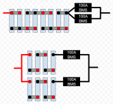
Screenshot - 2020-03-26 14-30-16.png

Cheers,
Jeremy
 
I think having 2 BMS on one battery would be better because theoretically they would both turn and off at the same time.

The problem with parallel BMS is what if one shuts down and the other does not. Now you are pulling same load through 1 BMS instead of 2.
 
The problem with parallel BMS is what if one shuts down and the other does not. Now you are pulling same load through 1 BMS instead of 2.

I think i have that problem in both configurations. These BMSs have an over-current protection that can shut them down too. So if I'm pulling peek load and one of them trips for whatever reason, the other is going to trip a moment later because of the"over-current" protection engaging. Not sure how quickly that engages and whether the BMS is at risk of frying before it does. Same is probably true of putting Battlebornes in parallel.
 
TBH your better off making 2 complete 4S packs each with a 4S BMS so they are free & independent of each other.
You can use one 4S BMS with paired cells but you lose "fine resolution" for the balancing of each cell and the fault tolerance aspect as well.
Generally it is wise to have a Higher Capacity BMS s that you do not take it to the edge of it's specs. 100A on a 12V system is only 1200W and that is not hard to hit. Turn on a coffee maker, microwave or similar and voila, your pulling 100A easily enough. So getting the higher amperage BMS will provide some buffer, if you "know" you will never pull more than 100A then 120A BMS is good BUT if you do pull 110A, the 120A BMS will be getting hot as it is close to it's performance spec.

Keep in mind as well, a proper balanced configuration will "Load Share" between the two packs, as well they will share the charge equally as well.
 
But I was thinking in situation one they should both have exact same readings therefore more likely to react in unison. In situation 2 the batteries are seperate and may give BMS different readings.
 
TBH your better off making 2 complete 4S packs each with a 4S BMS so they are free & independent of each other.
You can use one 4S BMS with paired cells but you lose "fine resolution" for the balancing of each cell and the fault tolerance aspect as well.
Generally it is wise to have a Higher Capacity BMS s that you do not take it to the edge of it's specs. 100A on a 12V system is only 1200W and that is not hard to hit. Turn on a coffee maker, microwave or similar and voila, your pulling 100A easily enough. So getting the higher amperage BMS will provide some buffer, if you "know" you will never pull more than 100A then 120A BMS is good BUT if you do pull 110A, the 120A BMS will be getting hot as it is close to it's performance spec.

Keep in mind as well, a proper balanced configuration will "Load Share" between the two packs, as well they will share the charge equally as well.
What I worry about is if one pack has a different IR one could shut off separate from other and create an overcurrent situation for other BMS. Ideally both BMS could handle max current. If one 150a bms suddenly has 200a will it smoke or just shut down IDK.

There is a reason we like Chargery lol
 
There is a reason we like Chargery lol

I have not fully read up on the Chargery. Is it using relays that remain energized the whole time? So i'd be loosing 50+ AH a day to that? Or does someone have a reference design that uses latching relays? Is there a budget-friendly option there?
 
Last edited:
I see what you are attempting to do...

You need 200 amp capability.

You seem to be attempting to share the load by paralleling the two 100 amp BMS.

I see an instant double failure if you ever draw 200 amps. That means one got more than 100 amps, and then the other one is left to dry to deal with now 200 amps. So instant double "trip" if one has more than 100 amps.

Why complicate the circuit with less than what you need? Why not get a 200+ amp BMS? Proper BMS's can be set to whatever you prefer with software. If you smash into the hardware limits of the BMS, then the BMS is done if it hits those amps.

I like the bottom drawing better than the top. I see both dead though if you draw 200+ amps.
 
What I worry about is if one pack has a different IR one could shut off separate from other and create an overcurrent situation for other BMS. Ideally both BMS could handle max current. If one 150a bms suddenly has 200a will it smoke or just shut down IDK.

There is a reason we like Chargery lol
Yes that is a key issue and yes the BMS' in my opinion should be able to handle the maximum draw that could be expected to prevent both from kicking off due to exceeding the capacity limits.

This becomes even more complex when one has different capacity Packs within a back. For example 100AH & 150AH packs. As one may discharge to the point of LVD cutoff, the other would still have remaining capacity to output. An inverter monitoring the line voltage would not know that Pack 1 shutdown and that it was drawing off Pack 2 because the Line Voltage does not indicate that, therefore the Inverter LVD would not be triggered.
LVD = Low Volt Disconnect..
 
If you have two battleborns in parallel that is going to be equivalent to #2. In other words if you have two independent 4S packs to make a bank the wiring will look exactly like #2. In the situation the BMS would just be hidden in a case. In short, #2 is the proper way to configure the system.
 
right. but i do appreciate the concerns about what happens in an over-current trip. One of the 2 BMSs will trip before the other - leaving the survivor to face 200% of rated capacity for a moment before it trips as well. Presumable, even battleborns would face this issue - and it comes down to how quickly the over-current protection is configured to act. Over current protection may be configured to act when the threshold has been exceeded to X milliseconds - which could well extend into several seconds perhaps. This would be to guard against nuisance trips from transient loads. Question is, does the BMS put out magic smoke before the protection trips?
 
right. but i do appreciate the concerns about what happens in an over-current trip. One of the 2 BMSs will trip before the other - leaving the survivor to face 200% of rated capacity for a moment before it trips as well. Presumable, even battleborns would face this issue - and it comes down to how quickly the over-current protection is configured to act. Over current protection may be configured to act when the threshold has been exceeded to X milliseconds - which could well extend into several seconds perhaps. This would be to guard against nuisance trips from transient loads. Question is, does the BMS put out magic smoke before the protection trips?
I understand the concern but I wouldn’t worry about that to be honest. You should, in this case, install a breaker on the main line to the inverter that limits current to less than the combined rating of the BMSs. At the end of the day the BMS is most useful to protect the battery at the cell level. The BMS really shouldn’t be relied on to provide over current protection for the entire system, just the individual packs. So the situation that would trip one BMS and not a main breaker would be pretty unlikely. If it did happen then you are correct, it would put the entire load on the remaining battery but that BMS will most likely trip almost instantly and it would probably still work.
 
Iam planning on building a 48V-300AH bank using 100AH cells and also was thinking pros-cons of a) 3 48V 100AH banks (16S3P), each with its own 100A BMS (Second diagram) or B) paralleling the cells (3P16S) and using a single 300A BMS (if I can find one).

I was leaning toward A) 3 48V batteries in parallel because of redundancy (3 batteries, each with a BMS) and if one failed I would still have a 200AH battery bank. But after reading this thread not so sure. If each battery has its own 100A breaker then would there really be a chance of cascading failures taking out all 3 BMS's
 
My advice which is what I've done is just use the bms for 12v applications and run the inverter with a relay providing it has a remote on/off switch. My max amps pull is around 135amps and this way I have full protection from the smart bms, and it only needs to handle my maxmium 12v which is 60amps. Running inverters through bms just seems pointless when it's easily avoided and allows you to use a $70 bms rather than a $200+. I do miss out on the SOC meter doing it this way, but you'll find all these funky toys are great to begin with but in the end you don't look at them or care, the best system is one that doesn't need monitoring.
 
The configuration in drawing 2 is what every BMS white paper recommends. But you should use some kind of contactor to protect the BMS.
 
Expanding on this line of thought. I am just getting started with setting up 16x 280ah cells for 12v and my thoughts were to have 4 separate "batteries" in a 4s configuration and a BMS for each one. I'm using the smart BMSs from ali rated at 120a with 3x10awg wire leads in and out. I want the 4 separate batteries for redundancy and so that the FET based BMSs are almost never loaded above 60%. Sailboat application and with regular loads and a 3kw inverter I can see the max draw around 260amps when fully utilizing the inverter. That won't happen very much but I'm sure it will for instance when using an induction cook top and a toaster at the same time, like to make eggs on toast. Four BMSs for longevity and redundancy but now I'm wondering if 1 or 2 cut out then the others are stressing. I'm thinking now maybe I should have 70amp breakers on each battery for overcurrent protection and at the time of drawing 260amps if more then one cuts out then they all will. Is this a good idea or should I have a current sensing device on each battery and a relay/contactor to kill the inverter?
 
Expanding on this line of thought. I am just getting started with setting up 16x 280ah cells for 12v and my thoughts were to have 4 separate "batteries" in a 4s configuration and a BMS for each one. I'm using the smart BMSs from ali rated at 120a with 3x10awg wire leads in and out. I want the 4 separate batteries for redundancy and so that the FET based BMSs are almost never loaded above 60%. Sailboat application and with regular loads and a 3kw inverter I can see the max draw around 260amps when fully utilizing the inverter. That won't happen very much but I'm sure it will for instance when using an induction cook top and a toaster at the same time, like to make eggs on toast. Four BMSs for longevity and redundancy but now I'm wondering if 1 or 2 cut out then the others are stressing. I'm thinking now maybe I should have 70amp breakers on each battery for overcurrent protection and at the time of drawing 260amps if more then one cuts out then they all will. Is this a good idea or should I have a current sensing device on each battery and a relay/contactor to kill the inverter?
I do this 4 battery thing with a 48V setup.

The advantage is that you have every cell being watched.
The disadvantage is that you have every cell being watched.

It is not any more complicated or complex, it is simply more monitoring.

If you do not want the expense of additional BMS or Balancers, just put the cell in parallel, and reduce the "batteries" to 2 or just one.

Always remember, as soon as you connect one cell to another cell, you just made one new cell. The new cell is either more voltage or can handle more amperage(or capacity).

Series adds volts
Parallel adds amperage(or capacity).

260 amps is massive for a 12V setup.

Please consider a 24V or 48V setup. If all you are doing is transforming 12VDC into AC with an inverter, you can drastically reduce amps and the cable size needed with 24V or 48V setups.
 
I do this 4 battery thing with a 48V setup.

260 amps is massive for a 12V setup.

Please consider a 24V or 48V setup. If all you are doing is transforming 12VDC into AC with an inverter, you can drastically reduce amps and the cable size needed with 24V or 48V setups.
Good to know thank you.

I'm sticking with 12v for simplicity, it's for a sailboat and everything runs off of 12v and I don't want to fiddle with extra equipment when I can get wire at a descent cost and the wire lengths are actually quite short.
 
if you have 2 battery's 4s connect them in parallel do you need to have a balancing board in-between them to keep those packs in sync
lets say a 8s active balancing board from helltech ?
I don’t think it’s possible y to run an 8s balancer across two 12v/4s packs that are running in parallel across each other.

I’m hoping that I’ll be corrected as running a single balancer like this would certainly reduce the expense.
 
Back
Top