diy solar

diy solar

2 Growatt SPF 5000 ES in parallel using 20 550W panels and 1 LifePO4 51.2V 200ah battery

you're right, my math was off by a decimal! sorry for that, i fixed it, final figure is Delta T of 69.6 (which translates to roughly -44.6 degrees after redacting the 25 STC).......
Still,
1) Do you get to -45 where you live?


2) Even if you did get to -45, you still haven't tackled the part related to WHY would the SCC would see it as a OPEN-CIRCUIT? is it a separate charge controller without inverter? is there no constant load on inverter? is it not an all-in-one inverter with SCC, MPPT, inverter, AC-DC charger? they way i see it, you should almost never have Zero load, the inverter alone consumes anywhere between 50 to 70 Watts, a baseline load (fridge, router, mobile charger, etc...) would constitute at least 250 ~300W on top of the inverter consumption at idle.....
The SCC pauses periodically and checks the voc, throughout the day. Every time it adjusts the MPP.
I assume that this is when it tripped on high bus voltage. Reducing to 10 panel strings fixed the issue.
 
Where is the thread that addresses this. I would like to read it. This week I updated both CPU's on my 4 Growatt SPF 5000 ES inverters to versions 040 06 C.01 for CPU1 and 041 06 C.01 for CPU2. I believe these are the latest versions available. My inverters so far have been maxing at 18.2 Amps. I will continue to watch them to see if that changes. The reason I updated was 3 of my 4 inverters would not start up with battery and PV power. The inverters have to be turned on to power up. At first only 1 inverter had this problem and after about 3 weeks of use 3 of my 4 inverters developed this problem. The update didn't fix the problem. I'm working closely with Signature Solar to try and resolve this problem. If anyone has a theory on what is wrong or what part might be burnt out on the inverters to cause this I would like to hear it.
 
0.2 to 0.3% Not 0.02 to 0.03%,/deg so @ 0 degrees delta would be 2.85V per panel, Not negligeable
i meant to say 0.02V which is the corresponding result of 0.2%
Also 2.85V is negligeable:
A) For 10 panels
B) For normal running condition (i.e. not VOC)

Gentlemen, VOC is only relevant upon installation and FIRST connect.......not on the long term "normal run scenario". Also at first sunlight early morning where one might see freezing temperatures, irradiance would not be at the peak, so whatever VOC increase at that particular time would mostly be compensated by the low irradiance, resulting in a lower voltage across the array.
A few exceptions might make the case here, this is why at design, one must steer away from absolute max limits by 10~15%, and that would mostly suffice.
I love how you are confident you are correct, and are willing to post recommendations for the entire internet to follow your advice that their equipment will be safe from overvoltage because of the ideas you arrive at.

VOC specs are published for safety, panels output the same voltage prior to load at very minimal luminance. Voltage limits are fairly strict, and exceeding them with any amperage can destroy electronics, insulation, and cause insane issues…
Why are you trying to get people to ignore the published warnings of EVERY BRAND OF EQUIPMENT PRODUCED?
I love how you attempt trolling your way into winning an argument that you seem to not have fully comprehended for the entire internet to give you a standing ovation.

I did not/ will never, get people to ignore published warnings of any brand of equipment, PERIOD! the discussion was way back around the variation of VOC due to temperature close to freezing, not VOC in GENERAL!
i advise you to read the beginning of the thread if you're interested to follow the trail of discussions rather than jumping to INCORRECT conclusions.
Interesting, you are now saying I am trolling when you have repeatedly in this thread suggested VOC won’t hurt because of various reasons…

You question scenarios because of constant load… ignoring the fact the load is on the battery bank, not the charge controller…

I am thrilled, your system handles 40V overvoltage potential… please stop recommending others will be as safe.

You advise I read to the beginning of the thread? I have been on this thread since post 4.
i was answering one question posted by a user confused as to why his SPF5000 was faulting with an OV only once during early hours, provided his system was rated with upwards of 450V for VOC, and he only had 12 panels outputting 36.5V @OC.... the whole thread ramified since then.
Long story short, he reduced the string to 10 & that seemed to have solved it.

On a side note, stop acting like 'king of safety' and accusing others of recklessness. I repeatedly explained that VOC is a value given by manufacturer, and it ONLY is relevant when in that state (i.e. OC). Anything else is not OC. A string connected to AIO such as SPF does not qualify as OC. I challenge you to post a photo of a meter reading the same voltage at the string terminals in both states (connected & disconnected).

you snatched a very specific reply i made to a very specific point, blew it out of context & proportion, and inaugurated yourself as "king of safety" looking down at us.
 
Gentlemen, VOC is only relevant upon installation and FIRST connect.......not on the long term "normal run scenario". Also at first sunlight early morning where one might see freezing temperatures, irradiance would not be at the peak, so whatever VOC increase at that particular time would mostly be compensated by the low irradiance, resulting in a lower voltage across the array.
A few exceptions might make the case here, this is why at design, one must steer away from absolute max limits by 10~15%, and that would mostly suffice.

Yeah, as someone in the north, I'm going to vehemently disagree with you on your first part. For one, Voc is on the charge controller once your battery is full. As soon as your battery is full, the charge controller can open circuit the input and you'll have Voc right there. I've aloe made a calculator in the past to calculate Voc for panels (there are other calculators as well). So if you take one of mine, 500W panels with a sticker Voc of 58.08V and Voc temperature coefficient of -0.29%/C (and power coefficient of -0.39%/C) you get a Voc on a typical winter day (-20C) of 65.6V (and 587.7W). And let me tell you, it doesn't take a lot of light to get to that voltage (power is another thing). So if you have a string of even two of these, you have a voltage that goes from sticker value of 116.16V to 131.2V. That's not insignificant, and that's something that you will see at the input of the charge controller on a regular basis.

I agree with your last sentence, but proper system design means taking this into account in every install, not just the few exceptions. You might assume you never it that kind of weather in your location, but ask some Texans about the reality of those assumptions...
I agree to almost all of what you've stated above, and you make excellent sense. However the original thread was opened with an AIO as the main inverter, specifically the SPF5000, which means:
1) the string is not connected to a standalone charge controller, but rather to an AIO inverter which on top of charging, supports loads, leading to an almost NEVER OC scenario. (P.S. SPF5000 consumes 60~70W at idle)
2) Why would batteries get to a FULL SOC so early in the morning? a decently sized battery bank/ inverter/ arrray, should suffice loads at night & be VERY hungry for a charge the moment sun rises, isn't it?
3) Extrapolating from point no.2, at early morning hours, the batteries start drawing every amp possible, leading to the PV's heating up & steering away & away from -20C (PV surface, not weather), hence dropping the string voltage further & further from max V.

This is an interesting discussion, awaiting your answer.
 
Last edited:
1) Doesn't matter that it's an AIO: internally it's still an MPPT + Inverter. However, imagine that the battery entered emergency cut-off for whatever reason at night, inverter shuts down. MPPT doesn't see the battery, and Voc is on the input.

2) Because you might have had a generator kick in because the battery was low, it recharged the battery and is now full. Or error condition like I mentioned in 1.

3) Yep, if nothing went wrong with the battery.
1) it matters, because the SPF can operate without batteries (albeit i don't have it connected that way due to power outages in my area, but still). Therefore, whenever batteries cut-off, they must "Auto-recover" or "auto restart" the moment charging input is present (be it utility or PV's). Also, don't forget the load side present at all times, & seen by the MPPT. On a side note, if the battery bank is Tubular lead-acid, "cut-off" is off the table as these don't have BMS's, & will simply go on to getting charged.

2) True.....if a gen is attached.....and it kicked in.....and it FULLY charged the bank......and you had Zero loads connected........you see where i'm going with this? lots of "if's".........not saying that it can't happen technically....just very unlikely.

3) Agreed.....again "IF"
 
That's the point of proper system design: some of those "if's" can cause major problems, so you want to make sure your design keeps them in consideration. Again, Texas comes to mind...
True, however engineering systems design are aimed at addressing the worst "Possible" scenarios, not EVERY thinkable scenario on the planet, unless you're building a space shuttle where the unknown is pretty much anything.
For instance, i'm designing a system installation for a house, that doesn't have/ will never have a generator, the "IF" of point no. 2 becomes irrelevant not an oversight.
Same thing goes for temperature drops, considering freezing temperatures where it never happens is not only irrelevant, but counter-productive...........again Abu Dhabi comes to mind.

i firmly believe designing an installation is very much dependent on what, where, & how......add to that, lessons learned from the community that are relevant to the what & where.

Of course - OP could be in Texas, or Canada. That's why details matter and why stating things like Voc non-trivially going up when it's cold matter in these kinds of discussions online.
 
Of course - OP could be in Texas, or Canada. That's why details matter and why stating things like Voc non-trivially going up when it's cold matter in these kinds of discussions online.
Agreed, albeit "non-trivially" doesn't apply to this thread. The user "carpediem80" who initiated the thread lives in a place near my childhood house (happy coincidence) where temperatures never go below freezing, & very rarely near freezing. My answer was customized to his specific scenario. we also had a lengthy chat privately pertaining to his case.

As i mentioned earlier, when threads get longer, discussions get ramified, and the original poster's pertaining scenario/question kind of fades a little.
 
i meant to say 0.02V which is the corresponding result of 0.2%
Also 2.85V is negligeable:
A) For 10 panels
B) For normal running condition (i.e. not VOC)

Gentlemen, VOC is only relevant upon installation and FIRST connect.......not on the long term "normal run scenario". Also at first sunlight early morning where one might see freezing temperatures, irradiance would not be at the peak, so whatever VOC increase at that particular time would mostly be compensated by the low irradiance, resulting in a lower voltage across the array.
A few exceptions might make the case here, this is why at design, one must steer away from absolute max limits by 10~15%, and that would mostly suffice.
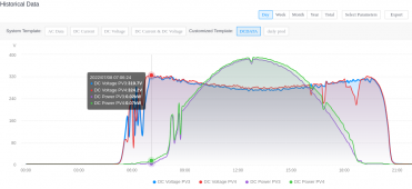
This is a graph of Voltage & Power of 2 strings of my inverter.
Screenshot from 2022-07-09 07-10-27.png
As you can see the voltage goes high (blue & red) without producing any power (green & purple).
Once it starts producing power the voltage drops and at the end of the day, current drops to almost zero and voltage goes up again.
Now imagine a night where it was freezing, you will see voltages above the VoC mentioned on the label of your panel, as that voltage is specified at 25C.
I know you probably are still not convinced, but just hoped to visualize it for you a bit.
 
This is a graph of Voltage & Power of 2 strings of my inverter.
View attachment 101882
As you can see the voltage goes high (blue & red) without producing any power (green & purple).
Once it starts producing power the voltage drops and at the end of the day, current drops to almost zero and voltage goes up again.
Now imagine a night where it was freezing, you will see voltages above the VoC mentioned on the label of your panel, as that voltage is specified at 25C.
I know you probably are still not convinced, but just hoped to visualize it for you a bit.
thank you for the graph, pretty neat actually. Which inverter is that? and is that from webview or app?

may we know a bit about this system's components/ architecture? starting with the strings arrangement, passing through the main components, all the way to the battery. And while you're at it, a screenshot of your PV label mentioning the VOC & TC.

Megarevo relabled hybrid unit (made by deye)
Currently grid tied only, am busy hooking up 4 x 48 volt/120Ah of batteries to it.

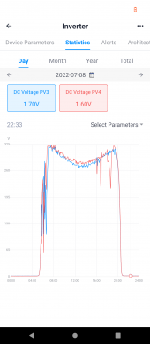
Graph comes from https://pro.solarmanpv.com/ because the inverter has a wifi data logger, so web based.
It also has an app of which this is a screenshot
Screenshot_20220709-074527.png

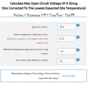
When I put the data of my panels and record minimum temperature in my area (southern california) in this calculator at
Screenshot from 2022-07-09 07-53-00.png
Max input voltage of string input is 500 volt but I prefer to not push it so I limit it to 450 volt hence my 12 in series.
I do have extra panels but intend to play it safe.
 
I have the 5000ES, and can confirm that the VOC is present in the morning and evening. And anytime the SCC resets to calculate MPP. (Seen on the screen of the inverter) I have watched it happen daily, for the last 6 months. I also had to reduce my strings panel quantity, to keep from tripping OVP. (Thankfully, that's all that happened)
 
Megarevo relabled hybrid unit (made by deye)
Currently grid tied only, am busy hooking up 4 x 48 volt/120Ah of batteries to it.

Graph comes from https://pro.solarmanpv.com/ because the inverter has a wifi data logger, so web based.
It also has an app of which this is a screenshot
View attachment 101886

When I put the data of my panels and record minimum temperature in my area (southern california) in this calculator at
View attachment 101887
Max input voltage of string input is 500 volt but I prefer to not push it so I limit it to 450 volt hence my 12 in series.
I do have extra panels but intend to play it safe.
Wow, thanks for the details! would love to see a photo of that beast of a battery bank once you're done hooking it up.

Notice the following:
your VOC (uncorrected) = 398.4V
your VOC (corrected for lowest temp) = 415.13V


your Voltage in your graph = 319.7V & 324.2V................................................Far Far from both "corrected & uncorrected VOC" because IT IS NOT VOC! simple!

I know you're probably not convinced, just thought of putting it out for you & from your own post, not mine.
 

Attachments

  • Screenshot 2022-07-09 200525.jpg
    Screenshot 2022-07-09 200525.jpg
    19.4 KB · Views: 7
Back
Top