diy solar

diy solar

2 Questions on connecting current carrying wires for JBD BMS - Connection and Amp allowed with two parallel 10 Gauge wire supplied

tsenator

New Member
Joined
Oct 5, 2021
Messages
26
I have 2 Questions on connecting current carrying wires for JBD BMS (in this case 100A Smart BMS) -

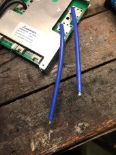
First Question -- How do you people wire these to the battery terminals or negative output battery post ? They are definitely too short as is to reach the terminals in my case I am using 100+AH prismatic Cells . I've seen some 'shoddy' soldering done by some Will Proust tear downs of batteries. I really would rather have a much cleaner connection. I have quality heavy gauge wire crimpers and I like the neatness of a good compression crimp. But what would I do? Strip back more insulation and double up the two wires into one heavy duty crimp and then use a 2 or 4 gauge wire on the other side ???

Come on people show me pics on how you did this ? Neatness and quality of connections are important to me .

Second question -- For you Electrical Engineers - How much current do these two 10 Gauge wires spec'ed to carry while in parallel ? Do you just add up the cross sectional area of the wires and get the closest wire gauges? 10 Gauge wire has cross sectional area of 5.26mm so doubling that is 10.5mm -- which is close to 7 gauges (Which is speced at max current about 90 A) ? Is that right ?
 

Attachments

  • BMS connections.jpg
    BMS connections.jpg
    238.3 KB · Views: 7
Maximum current carrying capacity is determined by the size of the conductor, (cross sectional area as you pointed out) & the combination of insulation type on the wire with regard to temperature tolerance. Also solid vs. stranded vs. fine stranded wire have to be factored in. Ultimately its about voltage drop and heat which is caused by resistance. The best way to design a system is to determine the amount of total voltage drop that is acceptable, for example 1.5% Etc. Then select the type of wire and gauge of wire accordingly based on calculations using the total length of the circuit.
Specifically, you were asking about 2 x 10Ga wires being adequate for 100A. An electrician would say that #10 wire is only good for a maximum 30A breaker. The pig tails on the BMS are short so there is not much resistance, I would be comfortable pushing them to 40A each intermittently but would NOT consider them suitable for 100A continuous duty cycle. This is just an opinion, I have not personally tested that BMS.
That would make a great follow up post if you could put the BMS under load at various current levels and test the temp of the wires.
I might just do that later after I get my big prismatic lifepo4 cells and tie it into an inverter with a 1200 watt hair dryer for a while.

Curious this hasn’t been brought up before by others here. This is a common way these popular BMS’s are cabled.
 
Those of us that bought our JBD BMS from Overkill Solar had the option to specify the number, gauge and length of the cables. The two BMS I ended up with had plenty of wire and capacity.

For your situation, there are a few options.
1. Connect the two BMS cables to a bus bar, then connect the bus bar to the battery
2. Put both BMS cables into a single ring terminal. Create a single cable from the battery with ring terminals on both ends. Connect the ring terminals.
3. Put a ring terminal on each BMS cable. Create a single cable from the battery with ring terminals on both ends. Connect the ring terminals.
 
This thread is cross-posted in the DIY LiFePO4 subforum. Please do not cross post.

 
Back
Top