The SCC would only output on the load terminal when the sun is shining. Not sure but someone said 20A but he wasn't sure about 24V. So, we would still need the batteries to power the DC loads when the sun isn't shining.Or you could posisbly return or sell the battery protect and use the load output for low voltage disconnect if it can be used that way, and can carry enough current for your DC loads (check the manual).


You are using an out of date browser. It may not display this or other websites correctly.
You should upgrade or use an alternative browser.
You should upgrade or use an alternative browser.
2000w, 24v solar system
- Thread starter guidecca
- Start date
In that case I would just ignore the load terminals altogether.The SCC would only output on the load terminal when the sun is shining. Not sure but someone said 20A but he wasn't sure about 24V. So, we would still need the batteries to power the DC loads when the sun isn't shining.
Go with something like:
Code:
Battery >> Busbar >> Battery Protect >> 24v to 12v converter >> fuse blockThat is a bummer.The SCC would only output on the load terminal when the sun is shining. Not sure but someone said 20A but he wasn't sure about 24V. So, we would still need the batteries to power the DC loads when the sun isn't shining.
The Victron SCC load output is basically just a battery protect built into the SCC with the battery protect being the same current as the charge current.
Once you go above 20A Victron deletes the load output.
One of the other members here was kind enough to check that the load output is not dependent on having a battery connected. I can use the solar panel and solar charger load output to run the ventilation fan without a battery being installed. Good for summer storage here.
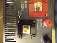
The Samlex inverter charger 2224 has four poles on the back; wires from battery go to the larger poles; wires from the solar charge controller go to the external charger poles.So, positive wire from battery to busbar. From positive busbar, one wire to Samlex inverter positive post and one positive wire to the DC side (breaker switch, battery protect, etc.). The Samlex has nothing to do with the DC side. I included a picture of a connection labeled "12V Output" that I think has nothing to do with the DC side. Would I be correct in those assumptions?Go with something like:
Code:Battery >> Busbar >> Battery Protect >> 24v to 12v converter >> fuse block
As for the battery protect, the purpose is to protect the battery from low voltage so shouldn't it be placed close to the battery on the DC side and disregard whether or not it is near the DC2DC converter.
Lastly, is a negative bus bar the same as a shunt? Can I ground components to both of them? Thank you.

Attachments
Last edited:
I think you are correct in those assumptions. I can't answer any specifics about the Samlex with any confidence, I've never owned one, what I can say is that they have great documentation, if you own one, you should definitely download and use the manual, its more than just a dry product manual, it is one part manual and one part how-to guide. It covers more than just the basic setup of the inverter, they do a good job of covering some big picture topics.The Samlex inverter charger 2224 has four poles on the back; wires from battery go to the larger poles; wires from the solar charge controller go to the external charger poles.So, positive wire from battery to busbar. From positive busbar, one wire to Samlex inverter positive post and one positive wire to the DC side (breaker switch, battery protect, etc.). The Samlex has nothing to do with the DC side. I included a picture of a connection labeled "12V Output" that I think has nothing to do with the DC side. Would I be correct in those assumptions?
I don't think it matters too much where you physically place it in the circuit. But yes you can place it closer to the battery if you want, this is probably a good idea. What's important is where it is positioned: between the battery and the DC loads. It needs to be able to cut power to the DC loads and only the DC loads, this is why locating it after the busbar is important.As for the battery protect, the purpose is to protect the battery from low voltage so shouldn't it be placed close to the battery on the DC side and disregard whether or not it is near the DC2DC converter.
I'm not entirely sure I'm following these two questions, can you clarify?Lastly, is a negative bus bar the same as a shunt? Can I ground components to both of them?
I'm not entirely sure I'm following these two questions, can you clarify?Lastly, is a negative bus bar the same as a shunt? Can I ground components to both of them?
I was wondering what the differences are between a shunt and a (black) negative bus bar. I believe the shunt is attached to the battery negative terminal and various monitors are attached to the shunt. The shunt and other components use the negative bus bar for ground, I believe. I'm not real clear on the difference between the shunt and the negative bus bar.
What shunt should I use? I bought the one in Will's list, 100A.
I have been checking and some people are using this one https://www.amazon.com/AiLi-Battery-Monitor-Voltmeter-Motorhome/dp/B07FGFFHC6?th=1 (350A).
I have been checking and some people are using this one https://www.amazon.com/AiLi-Battery-Monitor-Voltmeter-Motorhome/dp/B07FGFFHC6?th=1 (350A).
Check out the SOK 100AH lifePO4 deep cycle batteries (4000-8000 cycles, 7 yr. warranty, detachable cover/replaceable BMS or Cells, connect in series for 24V/36V/or 48V, low temp charging cut off, High temp or Discharging cut off, overcharging or disch. protection, over current and short circuit prot., battery cells auto balance, max charge current 50A, max discharge current 100A) before you buy. They are reported to be back in stock soon and are only $570 each!!Dzi, thank you! Your advice and the quick sketch are really appreciated. "Probably omissions and/or mistakes" withstanding, it is great progress forward for me. Except for the inverter can most of the original components in the video be used?
~ I am guessing that AC distribution would be important; would we plug devices into the back of the inverter or could the AC go to a breaker box? ~ Would you recommend an inverter or an inverter/charger? I don't recall that there was a way to charge batteries from shore power. Seems like it would be important if you are on the road and are running low. The inverters are cheaper.
~ Would two Battle Born LiFePO4 Deep Cycle, 100Ah 12v with built-in BMS, 3000-5000 Rechareable batteries in series work and could the system still be over-paneled in the future?
I'm not an A'hole, just busy trying to finish putting my first solar build together. I will answer later if it works when I turn on the multiple switches.I am also buying products for a 24V system. I'd appreciate any help with schematic that you end up doing that works. My initial system will only be 380-560 watts, but i"m overpurchasing components to grow.
Thank you for the wire/fuse information and your diagram. Just finished fixing a gas furnace for $40.00, but that was easy compared to this. Nothing to lose when fixing a broken furnace. Here, none of the components are broken, yet. Have ever used these: Blue Sea Systems MRBF Surface and Terminal Mount Fuse Block, https://www.amazon.com/gp/product/B0753F35Q8/ref=ox_sc_act_title_1?smid=ATVPDKIKX0DER&psc=1? I saw them on another system here in the forum. I am thinking about adding the van battery to charge the Battle Born batteries while driving.I have not, but that looks like extremely high quality.
I'm running all my positive wires through one busbar with no terminal fuses attached. Is the bus bar pole supposed to be loaded with fuses like this:

Have you ever used these: Blue Sea Systems MRBF Surface and Terminal Mount Fuse Block, https://www.amazon.com/gp/product/B0753F35Q8/ref=ox_sc_act_title_1?smid=ATVPDKIKX0DER&psc=1? I connected all of my positive wires to one bus bars but did not add fuses to the bus bar. I have a plain red bus bar; didn't know the poles were for fuses.I have not, but that looks like extremely high quality.
This Blue Sea Systems MRBF Surface and Terminal Mount Fuse Block, https://www.amazon.com/gp/product/B0753F35Q8/ref=ox_sc_act_title_1?smid=ATVPDKIKX0DER&psc=1? is loaded with fuses. Did not know bus bar was supposed to house surface fuses. Thinking I might need something other than a 175A fuse on the positive battery terminal. I added a 2 pole breaker to turn off the solar panels. Turned the on/off switch "on" between the battery bank and the red bus bar; the 175A fuse caught fire.I have not, but that looks like extremely high quality.
Does anyone have any advice or opinion on this simple straight-forward video?
. It uses two double-pole DC breakers and one double-pole AC breaker. The Samlex EVO Inverter-Charger 2224 has me connecting the Epever Tracer SCC to it. This simple inverter does not do things that way.
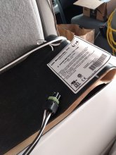
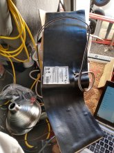
it is P/N: UHI Worldwide Inc. Z-25N60-BAT830-13V-15W with Battle Born's flair for including no documentation.Anyone know how to attach the heating blanket on the Battle Born batteries? It has some kind of connector; what does it connect to? I'll send a picture of it later.
Attachments
Last edited:
I believe it is optional whether you connect your SCC through the inverter or not. With the Samlex Evo. Its an option configuration that gives the inverter a bit more control over the broader system. But I don't believe you have to do it this way if you don't want to. Of course, you should double check, I don't own the Evo and am only going off my vague very limited understanding of the Evo.The Samlex EVO Inverter-Charger 2224 has me connecting the Epever Tracer SCC to it. This simple inverter does not do things that way.
Hi Dzi. Had a major short somewhere, not obvious, blowing a 175W fuse attached to the battery. If I'm not mistaken the battery terminal fuse can be located on either the positive or negative terminal. Jusbechillin, on this forum, set his system up with SCC connected to the EVO and everything seems to work. He used the Blue Sea Systems MRBF Surface and Terminal Mount Fuse Block, mentioned above; I use a common distribution busbar in my plan. We are going to troubleshoot it this weekend.
Similar threads
- Replies
- 4
- Views
- 157
- Replies
- 4
- Views
- 637
- Replies
- 15
- Views
- 283
- Replies
- 13
- Views
- 498
- Replies
- 4
- Views
- 238