12VoltInstalls
life passes by too quickly to not live in freedom
New thread to discuss nuetral-ground bonding of a Reliable 2000W inverter to continue the topic without hijacking a separate thread.
Posting here for lack of a better idea. Up in smoke?! Hope not?
Reliable (QZRELB) 2000W manual states that bare/green/G cannot be connected for a bonded system. Sortof.
@FilterGuy is compiling the oem state of various inverters here in case you want a reference for N-G bonding for this subject.
But does this mean you can’t bond it? I don’t know as the manual makes little sense:
With some critical thinking to discern meaning from the ambiguous broken english I interpret this biblically:
Others (not here) have suggested a high-value resistor in-line and a clamp meter to check for current but I see problems with that as I don’t have any burn relief cream on hand….
While I would love to resolve this for myself, the fact is the methodology of figuring out an inverter’s tolerance for N-G bonding should apply to every commodity inverter. And this is one of the more important considerations of any inverter installation whether mobile or ‘permanent.’
Posting here for lack of a better idea. Up in smoke?! Hope not?
Reliable (QZRELB) 2000W manual states that bare/green/G cannot be connected for a bonded system. Sortof.
@FilterGuy is compiling the oem state of various inverters here in case you want a reference for N-G bonding for this subject.
But does this mean you can’t bond it? I don’t know as the manual makes little sense:
Ya. I read it four or five times just now. Had to put my thinking cap on.very confusing
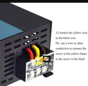
if the breaker ground line is combined with neutral, please connect it to the black wire on the inverter. It CANNOT connect the red and yellow or black and line to power the load
With some critical thinking to discern meaning from the ambiguous broken english I interpret this biblically:
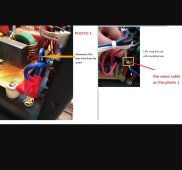
- “Breaker ground line” = bare/green/G wire from breaker panel
- “Is combined with nuetral” = N-G bond in breaker panel is acknowledged
- “Connect it to the black wire on the inverter” = (with what the manual states withstanding: “Note that the red is for hot, the black is for neutral, and the yellow is for ground) that they are instructing user to create a parallel path on G between inverter and breaker panel.
- “It CANNOT connect the….” = It being what? Referring to “breaker ground line” (sic) or the inverter itself. I have to surmise they are referring to the “breaker ground line” aka bare/green/G because of the ambiguity if stating that the inverter cannot power a load, right!
- “It CANNOT connect the red[H] and yellow[G] or black[N] and line[H,red] to power the load” = which means what exactly? Because N(black) to H(red) have to “power the load” as implied in 4. above. Which leads me to conclude that they mean one of three things and only one one makes sense because the other two make the inverter unusable.
- they are saying do not bond their inverter yellow[G] wire to black[N] on the inverter but leave it floating, and causing the yellow[G] to then carry lethal current.
- If one wishes to exit the inverter and connect immediately to a GFCI outlet to create protection before feeding the breaker panel (for a mobile system this would be desirable- even in a structure it would be desirable) one cannot safely establish the N-G in that outlet box
- The best case - in my case only, others may have different requirements to maintain safety- with my assuming the ambiguous instructions were discerned correctly would be to leave the inverter connection “open” and deadhead the bare/green/G with a wire nut at the inverter, and connect G to the GFCI with both the floating inverter end and the G to breaker panel. And depending on circumstances - and transfer switches or whatever - make the N-G in the GFCI outlet box ahead of any 3-pole transfer switch to effectively make the GFCI the ‘source of power’
- I would prefer to bond the inverter but with what the manual poorly says, I see no need to make the G ‘hot’ at the inverter; I’m not sure what that accomplishes?
Others (not here) have suggested a high-value resistor in-line and a clamp meter to check for current but I see problems with that as I don’t have any burn relief cream on hand….
While I would love to resolve this for myself, the fact is the methodology of figuring out an inverter’s tolerance for N-G bonding should apply to every commodity inverter. And this is one of the more important considerations of any inverter installation whether mobile or ‘permanent.’