My 200A BMS' have arrived from China, I ordered from Shenzhen E-Fire Technology Development Co., Ltd on Alibaba.
The listing's photos were the same as above / ebay / etc.
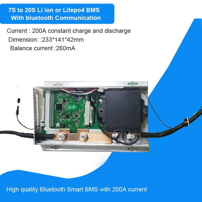
This unit is massive, almost the size of a 1L carton of milk, probably the size of a CALB grey 3.2V cell.
4.65cm * 11.77cm * 23.7cm
View attachment 20968 View attachment 20969
The cables are 11mm diameter with shrink wrap protected M10 hole copper lugs. The cable itself says 4AWG 200 deg C.
The Aluminium extrusion and end caps have scratches and scuffs of about the same cosmetic appearance that a Bitcoin ASIC miner arrives from China.
There are no mounting holes, unlike the advertisement picture and no opening/flap on the top.
Lily provided me with some manuals and wiring instructions for 8s, which were all in Chinese. I asked for the BMS leads to be labelled, which was done.
My batteries are still en-route by sea, and the battery boxes are to be fabricated. This BMS is so big it might not even fit inside the metal boxes I've ordered from Shenzhen Xuba with 8s 280Ah.
View attachment 20970
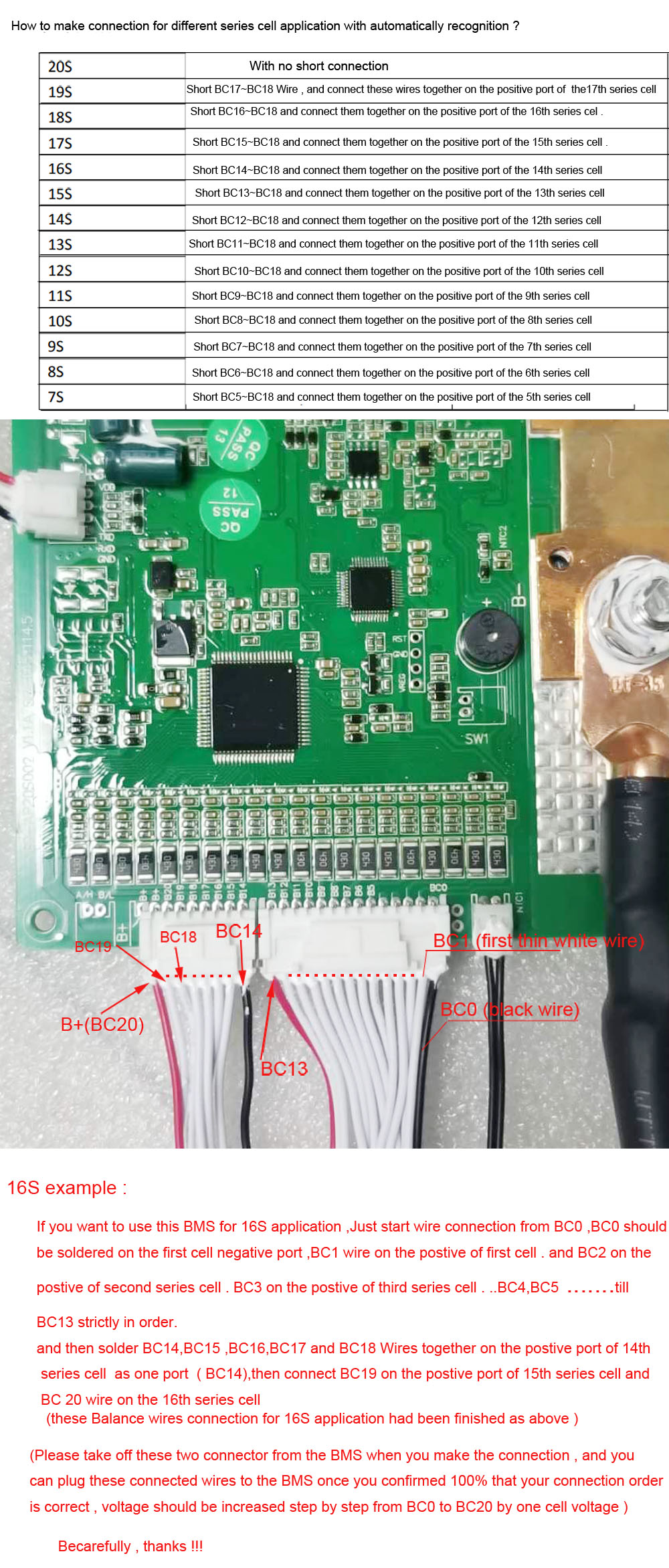
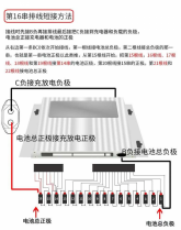
Here are the wiring documentation recieved.
View attachment 20973
My friend sent me this translation
And for this second image , the translation
View attachment 20972
View attachment 20976
With the leads pre-labelled by Shenzhen E-Fire it looks pretty self explanatory.
There are 22 wires from BC0-BC21
BC0 (wire #1) goes to cell 1 negative
BC1-BC5 go to cells 1-5 positive
BC6-BC18 go to cell 6 positive
BC19 goes to cell 7 positive
BC20-21 go to cell 8 positive