diy solar

diy solar

200A Smart BMS from LLT Power

Compared to other FET based BMS' 260 mA is actually on the high side:

Daly BMS35 mA
JBD Smart BMS (AKA Overkill Solar, etc)50 mA
Ant BMS100 mA

For context the two most popular non-FET-based BMS' on this forum are:
Electrodacus SBMS0150 mA
Chargery1,200 mA
 
It looks like it is using the same App as the one Overkill solar is selling.
 
It looks like it is using the same App as the one Overkill solar is selling.

I believe that website and the name LLT Power / LithiumBatteryPCB.com is one of a handful of confusingly branded brands of the company that manufactures the BMS sold be Overkill Solar and others.

Best I can tell after a bit of digging these are all the same entity or conglomerate:
  1. LLT Power / Lithium Battery PCB on the wide web
  2. Dongguan Jiabaida storefront on Alibaba
  3. JBD Battery PCB Storefront on Aliexpress
  4. The XiaoXiang BMS App (White and Blue Elephant Logo)
  5. "Dongguan Jiabaida Electronic Technology Co. Ltd."
  6. "Shenzhen LLT Electronic Technology Co. Ltd."

LLT Power / JBD LogoJBD Jiabaida LogoXiaoxiang BMS Logo
LLT logo.png
JBD logo.png
xiaoxiang logo.png
 
This info is very useful. So the balancing current is not so bad.

One good news is that this supplier actually supplies the JBD (overkill Solar BMS). So, the item has some potential to be reasonably good.
 
Updated BMS link


It looks to be the same as

 
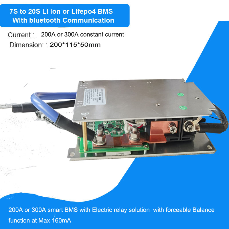
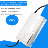
Hi! Anyone used this BMS from LLT Power: https://www.lithiumbatterypcb.com/product/7s-to-20s-200a-smart-bluetooth-bms/
Model No: JBD-AP20S002

Looks like a good bargain, what your views?

View attachment 18897

My 200A BMS' have arrived from China, I ordered from Shenzhen E-Fire Technology Development Co., Ltd on Alibaba.

The listing's photos were the same as above / ebay / etc.

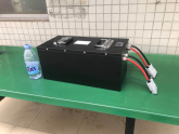
This unit is massive, almost the size of a 1L carton of milk, probably the size of a CALB grey 3.2V cell.
4.65cm * 11.77cm * 23.7cm
20200826_153955.jpg 20200826_154026.jpg

The cables are 11mm diameter with shrink wrap protected M10 hole copper lugs. The cable itself says 4AWG 200 deg C.

The Aluminium extrusion and end caps have scratches and scuffs of about the same cosmetic appearance that a Bitcoin ASIC miner arrives from China.

There are no mounting holes, unlike the advertisement picture and no opening/flap on the top.

Lily provided me with some manuals and wiring instructions for 8s, which were all in Chinese. I asked for the BMS leads to be labelled, which was done.

My batteries are still en-route by sea, and the battery boxes are to be fabricated. This BMS is so big it might not even fit inside the metal boxes I've ordered from Shenzhen Xuba with 8s 280Ah.
0.png

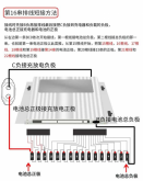
Here are the wiring documentation recieved.
IMG-20200819-WA0000.jpg
My friend sent me this translation

When connecting the wires:
First, connect the “B負”(B-) to the “電池總負極”(total battery -),then the “排線”(cable series?).
Next, connect “C負”(C-) to the “充電器負極”(charger-).
Last, connect “電池總正極”(total battery +) to the “充電器正極”(charger+).
————————-
“排線”(cable series):
Starting from the right, connect wire to:
Wire-1: 電池總負極(total battery -)
Wire-2:第一串電池正極(battery series 1)
Wire-3: 第二串電池正極(battery series 2)
Wire-4: 第三串電池正極(battery series 3)
Wire-5: 第四串電池正極(battery series 4)
Wire-6: 第五串電池正極(battery series 5)
Wire-7 to Wire-19: 第六串電池正極(battery series 6)
Wire-20: 第七串電池正極(battery series 7)
Wire-21 &Wire-22: 電池總正極(total battery +)


And for this second image , the translation
IMG-20200819-WA0004.jpg
The instruction is pretty much the same as the other one.
Connect every extra battery using wire-7 to wire-19.
Only difference on this table is that: J3 “未使用”(not used).
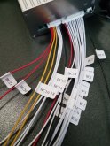
IMG_20200826_165453.jpg
With the leads pre-labelled by Shenzhen E-Fire it looks pretty self explanatory.

There are 22 wires from BC0-BC21
BC0 (wire #1) goes to cell 1 negative
BC1-BC5 go to cells 1-5 positive
BC6-BC18 go to cell 6 positive
BC19 goes to cell 7 positive
BC20-21 go to cell 8 positive
 

Attachments

  • c6c4c759242ed24eab7c1980cb6e6719.pdf
    967.5 KB · Views: 127
  • JBD-AP20S002-P20S-200A-B-U V1.1.pdf
    465.4 KB · Views: 120
Last edited:
I had originally be planning to build 2 x 8s packs, all still en route at the moment.

I have ordered a larger 5kw charger/inverter which requires 48V, Lily has sent me the 16s wiring diagram for this BMS

1599304019064.png
 
Don't like BMS's with solenoid based cutout switch.
I don't know enough about switches, relays and solenoids to understand why one maybe more reliable than another.

From the OP lithiumbatterypcb description
  • We adopted the electric relay solution for power controlling switch instead of Mosfet ,with 300V withstanding voltage
  • Precise SOC calculation with SOC function of automatic learning
  • Automatically charge battery function or static balance function for the battery system
  • Equipped with Bluetooth communication function for monitor all battery information clearly from APP or PC .( RS485 communication and CAN communication can be added on this board if needs )
  • with reserved Swith function to controlling the battery output ,the discharge cotrolling switch will prevent fire sparking when connects charger .
  • when the battery rest time reached its setup time of the rest . the bms will turn off and went to sleep mode so as to low the current consumption in rest period
 
I dont see anywhere that there are wires to power a contactor unless that is the black wire on the top of the picture. I guess they switch the negative.
 
Don't like BMS's with solenoid based cutout switch.
I don't know enough about switches, relays and solenoids to understand why one maybe more reliable than another.

@RCinFLA could you elaborate. I also don't know enough about the particulars of switches or BMS topology to understand the pros/cons. If solenoid based is synonymous with relay based, I don't understand your dislike, it seems to be the go-to solution for higher end or higher current BMSes.

@AussieSim I had assumed this was a FET based BMS. But it sounds like it is not. Is the 'electric relay' external or internal? If it is not FET based, I wonder what the big ole' aluminum heatsink is all about. I don't believe I have seen any non-FET-based BMSes that had large heatsinks.
 
Last edited:
A relay or contactor typically requires some current to hold it in. The description on this one says it is "magnetic latching" which eliminates the holding current issue. The relay does look fairly large. It is actually inside of the case, which is why it is so large. The question comes down to the quality of the contact material and how well they are held together in the latched on position. Too bad they didn't include active balancing.
 
A further read of this thread and I realized the device that is the subject of this thread is all contained in one package with the contactor.
 
Back
Top