diy solar

diy solar

200w solar system expectations...

You can change an entire lighting circuit to 12 by removing it from the consumer unit. Keep it a ring and you can connect to the battery wherever you want. Make sure you still use a fuse though.

You can get adapters for most bulb fittings so you can use a 12v GU10 or MR16 bulbs of which there are many types and fairly cheap.

Oh yeah, just checking - you're in UK? Pretty sure I can tell but I don't think you've put a location.
Hi there wow that does sound interesting... Not sure my three 100w panels would power the house ring main yet but I'm getting there haha!

Yeah I'm in UK ?
 
Interestingly...

It's a nice sunny day and the battery is now fully charged even with lights running inside and the Amps going in is varying but hits around 8amps.... I'm assuming this is still nowhere near what my 3 panels should be churning out though so need to get up there and have a look!
 
Hi there wow that does sound interesting... Not sure my three 100w panels would power the house ring main yet but I'm getting there haha!

Yeah I'm in UK ?
The lighting is normally on its own circuit separate to the sockets. You would need to check that though. Sometimes people are a bit naughty with new sockets or lights. Changing 240v to 12v is the safe way round though.
 
Quick question... I have the panels wired in parallel with a 3-1 connector with an in-line fuse on each one... Am I able to simply disconnect the panels at the roof and test them with a multimeter as a group of 3 and individually for the amps coming through?
 
Yup, it's going to be a lot of up & down the ladder unfortunately.

Lets call them Panel 1, on the far left, Panel 2 in the middle, and Panel 3 on the right.
Drain some off the battery so it wants a real charge, 12.5v-12.7v ought to be about perfect
Unplug 2 & 3 and measure the voltage on Panel 1's connectors, and go see what the controller says for Amps
Repeat with panel 2 and again with panel 3
That will tell you if one of your panels is dead, you Should see about the same volts at the connectors and amps coming in from each one.
If all 3 are reading the same, go plug in 1 & 2 and see what the amps are, then repeat for 2&3 and 1&3
Hopefully you Should see about 2x the amps as you were seeing from each panel alone. If not there are other problems.

Post what you see out of the panels as you perform the tests, we'll go from there.

There have been instances where due to weird wiring panels would work great alone or in series but totally refused to play in parallel.
 
Interestingly...

It's a nice sunny day and the battery is now fully charged even with lights running inside and the Amps going in is varying but hits around 8amps.... I'm assuming this is still nowhere near what my 3 panels should be churning out though so need to get up there and have a look!
Yes, this is what you can expect. Your panels are not at the right angle towards the sun and your location is crap, and both settings you cannot change LOL.
Buy yourself a DC clamp Amperemeter, this is an amazing tool to measure current.
You can see, my setup is very similar, and I get Spain sun, and 5A per panel I have never seen.
 
Yup, it's going to be a lot of up & down the ladder unfortunately.

Lets call them Panel 1, on the far left, Panel 2 in the middle, and Panel 3 on the right.
Drain some off the battery so it wants a real charge, 12.5v-12.7v ought to be about perfect
Unplug 2 & 3 and measure the voltage on Panel 1's connectors, and go see what the controller says for Amps
Repeat with panel 2 and again with panel 3
That will tell you if one of your panels is dead, you Should see about the same volts at the connectors and amps coming in from each one.
If all 3 are reading the same, go plug in 1 & 2 and see what the amps are, then repeat for 2&3 and 1&3
Hopefully you Should see about 2x the amps as you were seeing from each panel alone. If not there are other problems.

Post what you see out of the panels as you perform the tests, we'll go from there.

There have been instances where due to weird wiring panels would work great alone or in series but totally refused to play in parallel.
Hey thanks I really appreciate this... Makes perfect sense. Will sort this out asap... Hopefully tomorrow.

I'd be really disappointed if one of the panels had died because they're fairly new!

I've also ordered an mppt controller so this will help when it comes!
 
Yes, this is what you can expect. Your panels are not at the right angle towards the sun and your location is crap, and both settings you cannot change LOL.
Buy yourself a DC clamp Amperemeter, this is an amazing tool to measure current.
You can see, my setup is very similar, and I get Spain sun, and 5A per panel I have never seen.
Thanks very much - I've ordered one of these amperemeters they look great to save messing with disconnecting wires etc.

Interesting that you don't see 5a per panel... I've got no chance then ? ... But I will get them raised up more by the weekend definitely!

I have two 110ah batteries connected thinking that I'd get a few days worth of juice even in really overcast weather like our winters, but now I'm wondering if it will be even usable! My thoughts were.... 110ah x2 = 220ah... But 50% useable so back to 110ah.
 
.... Then my thinking was that at 220v after the inverter 1 amp = 220watts... So I would have 220w x 110ah = 24,200wh. With the inverter inefficiency for converting maybe leaving 85% of this so 24,200 x 0.85 = 20,570wh. ... Or approximately 20,000wh.

Then if I was using lights +other loads at say 200w then that would give me 100hours of continuous usage without being charged...

Where am I going wrong here?! (I'm very aware that my amateurism may give some experts here a good chuckle and I'm fine with that ??) . I've watched many videos on YouTube about a this as my 'homework' before setting up but there's only so much YouTube can teach you ?


I must say thanks SO much for a the replies so far from everybody .... All massively useful.
 
.... Then my thinking was that at 220v after the inverter 1 amp = 220watts... So I would have 220w x 110ah = 24,200wh.
yeah, that would be nice, BUT to have 1A at 220V, you need to draw 10A from your 12V battery. That's the catch here.
So you need to calculate everything from 12V, because that's where your energy comes from. Minus 10 or 20% which are the losses in cables and inverter.
 
Then my thinking was that at 220v after the inverter 1 amp = 220watts... So I would have 220w x 110ah = 24,200wh. With the inverter inefficiency for converting maybe leaving 85% of this so 24,200 x 0.85 = 20,570wh. ... Or approximately 20,000wh.
I wish it worked that way, but unfortunately not. The math is for the battery capacity, so 110Ah @ 12v = 1320Wh the battery can hold. If you convert that to your 220AC then you have 1320Wh / 220v = 6Hr of runtime at full load... perfect world napkin math. Your math would work right if you had a 220v battery holding 110Ah, but such a thing is really REALLY rare and expensive and weird and lab built. :)
 
The lighting is normally on its own circuit separate to the sockets. You would need to check that though. Sometimes people are a bit naughty with new sockets or lights. Changing 240v to 12v is the safe way round though.
Where are you from??!! Every house I've lived in or worked on has ALWAYS "Saved Money" by tying the outlets into the lighting circuits and de-rating the outlets. It's the cheapest option under NEC. :(

And people wonder WHY I want to run separate outlet and light circuits... grrrr....
 
Yup, it's going to be a lot of up & down the ladder unfortunately.

Lets call them Panel 1, on the far left, Panel 2 in the middle, and Panel 3 on the right.
Drain some off the battery so it wants a real charge, 12.5v-12.7v ought to be about perfect
Unplug 2 & 3 and measure the voltage on Panel 1's connectors, and go see what the controller says for Amps
Repeat with panel 2 and again with panel 3
That will tell you if one of your panels is dead, you Should see about the same volts at the connectors and amps coming in from each one.
If all 3 are reading the same, go plug in 1 & 2 and see what the amps are, then repeat for 2&3 and 1&3
Hopefully you Should see about 2x the amps as you were seeing from each panel alone. If not there are other problems.

Post what you see out of the panels as you perform the tests, we'll go from there.

There have been instances where due to weird wiring panels would work great alone or in series but totally refused to play in parallel.
yeah, that would be nice, BUT to have 1A at 220V, you need to draw 10A from your 12V battery. That's the catch here.
So you need to calculate everything from 12V, because that's where your energy comes from. Minus 10 or 20% which are the losses in cables and inverter.
Thanks conquistador... Now that makes more sense of my real life findings ? Really glad to have learnt that, although gutted compared to my original magical land figures ?
 
Just as a reference, other panels have had similar issues working in parallel so it could very well be the panels. Hopefully your new MPPT controller will sort it all out.
It could be that the panels are badly designed and have huge differences in voltage and internal resistance. In this case diodes in series with each panel will help.
However, my guess is the location and the inclination of the panels combined with low radiation make it like it is . The panels will only output their rated Wattage at 3000m high with loads of UV and air temperature of 0°C. In hazy conditions with a wrong angle to the sun, you will get much less.
Crossy seems an exception, but he doesnt have the inclination issue.
This gentleman seems to have much lower output. All really depends on the location and UV conditions I would say.
 
Just as a reference, other panels have had similar issues working in parallel so it could very well be the panels. Hopefully your new MPPT controller will sort it all out.
I hope so too - it's in the way in the post and I'm quite excited about it! ? ... Haven't been up to getting on the roof today to check the panels separately so it's looking like that's a mission for this weekend whilst I also tilt them up further ?
 
I wish it worked that way, but unfortunately not. The math is for the battery capacity, so 110Ah @ 12v = 1320Wh the battery can hold. If you convert that to your 220AC then you have 1320Wh / 220v = 6Hr of runtime at full load... perfect world napkin math. Your math would work right if you had a 220v battery holding 110Ah, but such a thing is really REALLY rare and expensive and weird and lab built. :)
Just thinking about this... Maybe another battery is the way forward for the winter. I didn't want to invest too much into these as I'm just testing to see how long they last as these 110ah lead acid 'solar' batteries were around £70 each... Much more affordablenfor me at the moment than the proper deep cycle solar batteries.
 
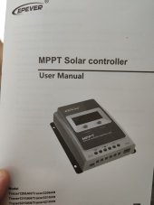
Ok so the new mppt controller just arrived ?

I have a few safety questions after reading through, I hope somebody can help me with these...
1. Do I need to buy a fuse for the battery positive line before I install the mppt controller or will it be ok to install whilst I order a fuse? Any links to a good one would be much appreciated as I'm not exactly sure what type is best.
2. Do I need to ground the inverter/battery at the battery negative terminal with a grounding rod?
3. The diagram of the setup seems to has a fuse on each positive AND negative wire going to each solar panel... Is this necessary? I have a fuse on each positive at the moment before they connect in parallel.

Thanks so much for all help so far... Might be able to get some decent usage out of the system with the mppt SCC onboard!
 

Attachments

  • IMG_20220526_145351.jpg
    IMG_20220526_145351.jpg
    81.1 KB · Views: 4
Ok so the new mppt controller just arrived ?

I have a few safety questions after reading through, I hope somebody can help me with these...
OK, shoot!
1. Do I need to buy a fuse for the battery positive line before I install the mppt controller or will it be ok to install whilst I order a fuse? Any links to a good one would be much appreciated as I'm not exactly sure what type is best.
In a perfect world yes, you would have a fuse between the Batt+ and the battery to protect the wire between the two. IMO if your wire is over-spec for the max amperage the SCC can produce then the fuse can just get put on order and you can throw it in when it arrives.
2. Do I need to ground the inverter/battery at the battery negative terminal with a grounding rod?
If your inverter is feeding to a breaker box then the breaker box should have a ground bar that is connected to the inverter already. If not then you'll want to connect something to that ground screw on the end of your inverter to some sort of grounding system in the house like a water pipe or the like, or a plate in the ground, or something. When it comes to grounding there are about 50 ways to do it right, 1500 ways to do it wrong, and 3000 ways to do it kinda-ish-good-enough. Fortunately I've never heard of someone's house burning to the ground because their rod was only2.92m instead of the required 3m. Momentarily someone will be along to tell me I'm wrong though.

Long and short of it, no you do NOT want to connect your Batt- to ground in your case. If this was a vehicle then you would connect it to the chassis.
3. The diagram of the setup seems to has a fuse on each positive AND negative wire going to each solar panel... Is this necessary? I have a fuse on each positive at the moment before they connect in parallel.
The only time you need fuses is if you are doing 3 or more strings, and even then only on the + side like you have now. Now that you've got the MPPT controller you can set up your panels in series and just have a single 3s string to the SCC. As long as you can keep the shade off that should net you the maximum wattage out of your 3 panels AND gets around any weird no-paralleling-diode issues.
Thanks so much for all help so far... Might be able to get some decent usage out of the system with the mppt SCC onboard!
Yeah, you should see a noticeable improvement right out the gate. Considering what you've been fighting anything over 3a or 36w is going to be gravy. :)

You did tilt your panels to face the sun better, right?
 
Last edited:
OK, shoot!

In a perfect world yes, you would have a fuse between the Batt+ and the battery to protect the wire between the two. IMO if your wire is over-spec for the max amperage the SCC can produce then the fuse can just get put on order and you can throw it in when it arrives.

If your inverter is feeding to a breaker box then the breaker box should have a ground bar that is connected to the inverter already. If not then you'll want to connect something to that ground screw on the end of your inverter to some sort of grounding system in the house like a water pipe or the like, or a plate in the ground, or something. When it comes to grounding there are about 50 ways to do it right, 1500 ways to do it wrong, and 3000 ways to do it kinda-ish-good-enough. Fortunately I've never heard of someone's house burning to the ground because their rod was only2.92m instead of the required 3m. Momentarily someone will be along to tell me I'm wrong though.

Long and short of it, no you do NOT want to connect your Batt- to ground in your case. If this was a vehicle then you would connect it to the chassis.

The only time you need fuses is if you are doing 3 or more strings, and even then only on the + side like you have now. Now that you've got the MPPT controller you can set up your panels in series and just have a single 3s string to the SCC. As long as you can keep the shade off that should net you the maximum wattage out of your 3 panels AND gets around any weird no-paralleling-diode issues.

Yeah, you should see a noticeable improvement right out the gate. Considering what you've been fighting anything over 3a or 36w is going to be gravy. :)

You did tilt your panels to face the sun better, right?
This is SO helpful thank you!!!

Right... Well I've installed the new mppt controller... Battery first then panels.

Interestingly it's reading the same input from the panels as the pwm from a few moments ago (both reading input of about 3 amps... It's overcast but this seems pretty poor ?). I haven't moved the panels up more yet but might try to do this now while I'm at it.

Weirdly the new mppt SCC is saying there is a 0.2a load with nothing switched on, not even the inverter ?

Will go move the panels now (still connected in parallel!)
 
Back
Top