diy solar

diy solar

22' travel trailer design

jimcalf

New Member
Joined
Aug 1, 2020
Messages
73
Location
Akron, OH
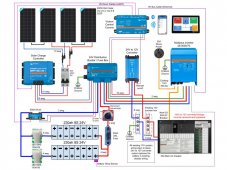
Hi All, I've ordered the battery cells and BMSs from China. Now while waiting I'm finalizing the design. Will be going into a Small 22' travel trailer, but plenty of room in the under bed/passthrough storage, so components will be close together and cables will be quite short. Prewired on the roof w/MC4 and 10 awg wiring. Can you spot anything that I'm getting wrong or missing outright?
2108TB Li Schematic.jpg
 
Since you've chosen lithium batteries you should have a Class T fuse, not ANL.

Enjoy,

Perry
 
Since you've chosen lithium batteries you should have a Class T fuse, not ANL.

Enjoy,

Perry
Thanks. I saw a lot of guidance saying if you have 12V, T Class isn't needed. 48V, definitely need T Class, but nobody ever talked about 24V. Could go either way I guess. Easy enough to swap that out.
 
I'm not seeing circuit breakers on the output side of the MPPT and the input side of the Multiplus. If you have sufficient fuses inside the Lynx for the inverter/charger that may be OK. But the wire on the output side of the MPPT isn't protected. Putting the fuse at the end of the wire doesn't help protect the wire.

The 63 amp circuit breaker between the solar panels and the MPPT is too high. It should be closer to 20 amps, probably 25 amps to avoid the nuisance trips.
 
Really think your battery wires are too small. 3000 volt amp inverter is actually 2400 continuous. If these batteries are run to a low SOC, the voltage will drop to as low as possibly 10 volts. THat’s 240 amps, plus another 15% for inverter losses for a around 276 amps. Wiring inverters for me has been more about ampacity than voltage loss.

So, I am planning on wiring my similarly sized inverter at 2 AWG for battery interconnect wire and 4 AWG after the batteries are combined to the inverter.


4A29442C-5156-4D75-873D-E8FA2729AF46.jpeg
Also recommend the much bigger much more expensive with a higher AIC rated Class T fuse. If operating at lower ends of SOC, you could also easily exceed 200 amps.

I have VIctron equipment and for the Disribution / fuse box, I went with busbars and fuses. The central com is not necessary, unless the Multiplus requires it, but looks like this provides quite a bit of information.

The converter you list should work with the wire you listed provided ampacity is not an issue. I have the 70 amp VIctron converter which requires thicker than the 6 AWG you list.
 
I'm not seeing circuit breakers on the output side of the MPPT and the input side of the Multiplus. If you have sufficient fuses inside the Lynx for the inverter/charger that may be OK. But the wire on the output side of the MPPT isn't protected. Putting the fuse at the end of the wire doesn't help protect the wire.

The 63 amp circuit breaker between the solar panels and the MPPT is too high. It should be closer to 20 amps, probably 25 amps to avoid the nuisance trips.
Thanks for the feedback. I'll recalculate the amperages and rectify that on both sides of the MPPT controller. I had just planned on putting a 50A fuse in the Lynx, and the wire is short, as the boxes are right next to each other. On the 24V side, I had calculated that the max current is about 38amps. The wiring should be no more than a foot or two, but I'll do the math again to make sure the wire has plenty of overhead over 50amps. I still have to do the component layout before I really know though.
 
Really think your battery wires are too small. 3000 volt amp inverter is actually 2400 continuous. If these batteries are run to a low SOC, the voltage will drop to as low as possibly 10 volts. THat’s 240 amps, plus another 15% for inverter losses for a around 276 amps. Wiring inverters for me has been more about ampacity than voltage loss.

So, I am planning on wiring my similarly sized inverter at 2 AWG for battery interconnect wire and 4 AWG after the batteries are combined to the inverter.


View attachment 69975
Also recommend the much bigger much more expensive with a higher AIC rated Class T fuse. If operating at lower ends of SOC, you could also easily exceed 200 amps.

I have VIctron equipment and for the Disribution / fuse box, I went with busbars and fuses. The central com is not necessary, unless the Multiplus requires it, but looks like this provides quite a bit of information.

The converter you list should work with the wire you listed provided ampacity is not an issue. I have the 70 amp VIctron converter which requires thicker than the 6 AWG you list
I'm surprised that you think a 24V battery would get down to 10 volts at low SOC. Are you thinking this is a 12V configuration? While I haven't finalized my config for the BMS and inverter/charger low voltage cutoffs, somewhere around 22V (or higher) would be more normal for LiFePo4.
Based on that, would you change your recommendation?
thanks
 
t down to 10 volts at low SOC.
Bad Math using the 12 volts. Using 20 volts as a low cutoff, I would still change that to thicker. If you have safeties to keep it from getting that low, then the wires could be thinner.

The 20 volts depends on a couple of things. First you’d have to be the cells set to a low voltage cutoff of 2.5 volts. That would come out to 20 volts. THere’s also the BMS low voltage setting. Then finally the inverter would have to have a 20 volt low voltage cutoff.

If you tried to pull 3000 watts at that 20 volts, that would be 150 amps, plus 15% inverter loses, so around 172 amps Pulled from the battery. That comes out to 2/0. THat also has no safety factor.

Yesterday, I have a smaller lithium bank I ran while away at work, and the batteries died on it. The solar panels became unplugged. So this thing reaced a low voltage that the inverter pulled more amps from. Could have been around 20 volts. Unfortunately, the BMS logs no data, so I don’t know for sure.

Probably the only time that inverter and battery will ever reach those low volts, but the design was there to handle it with thicker wire and fuses.

If you have some safeties built in to cut the voltage off at 22 volts, like BMS settings for cells and minimum voltage, and you trust this before it gets to the lower inverter minimum cutoff voltage, then that may work.
 
Thanks. I saw a lot of guidance saying if you have 12V, T Class isn't needed. 48V, definitely need T Class, but nobody ever talked about 24V. Could go either way I guess. Easy enough to swap that out.
From a voltage perspective, my understanding is an ANL fuse is rated to 80Vdc
 
From a voltage perspective, my understanding is an ANL fuse is rated to 80Vdc

I sure would like to see some real world testing. The topic of which fuse type to use comes up often and I have three responses to use for Class T:
1. It's what is recommended
2. It has the highest AIC rating
3. It's what I'm using

It's hard to argue that an ANL fuse isn't "good enough" when it shows up on most of the Victron diagrams.
 
I would also add a 35-40A dual pole AC breaker (for the hot and line wires) between the 30A shore power plug and the inverter's AC-in. This adds an extra level a safety just incase you ever connect to a faulty campground power outlet.
 
Back
Top