diy solar

diy solar

24v DC auto transfer switch?

Sorikan

New Member
Joined
Sep 15, 2021
Messages
6
I have a refrigerator that is 24v dc powered. It is currently running off of a 110 to 24v power supply. I am building a 24v LiFePo4 battery to power it when the power fails. I would like to find a device where by it switches between two different 24v sources in order to power the refrigerator no matter what happens.

It does not need to charge a battery, or anything else for that matter. Just automatically switch between 24v DC sources. Does such a thing exist?

Also, does a 24v DC circuit failure alarm exist? IE, like the devices you can plug into an outlet or power strip which will sound a siren or buzzer when they lose 110 power - as they have a 9v for the siren when power goes out.

Thanks for reading!
Will you be using a charger to charge the battery from 110v? If it has enough current to power the frig, just hook it to your battery and then hook the frig to the battery. If power goes out the battery will supply the power. When power comes back on the charger will charge the battery and run the fridge.
 
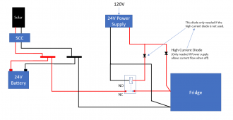
This might work (But no alarm).

Edit Added diodes to prevent back-flow of currents.
NOTE: If implementing a relay only circuit (No battery protect), the double throw relay suggestion from @time2roll is probably better. (See post 7)

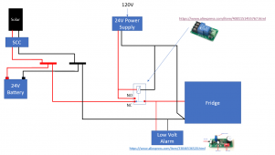
1631814331907.png
(Be sure your power supply does not let current backflow if it is not plugged in)

When the 24V power supply is powering things, the normally closed relay is open. If the 24V power supply goes out, the battery gets connected.


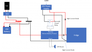
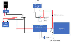
I am not sure how you want to use the alarm, but the Victron Battery protect has alarm outputs. You could do something like this:

EDIT: Added diodes to prevent backflow of current.

View attachment 64973
 
Last edited:
Any DPDT relay will work. Maybe this one: https://www.digikey.com/en/products/detail/industrialemart/HR723-2C-24VDC/13182599

connect the 24v coil to the 24v utility supply to connect power through the NO contacts.
connect the battery to the NC contacts.

When you lose utility power the relay will switch to battery. Contact rating is 30 amps DC. Do you need more?
You posted while I was still drawing. ?

Edit: I completely changed the remainder of the post. (My original circuit was flawed)

In my original circuit for both the battery protect and a single throw relay, the power from the battery would turn the relay back on...taking away the battery power. You would get a constant chatter of the relay..... In my above post I added Diodes to prevent that but if you are doing a relay only (no battery protect) solution, the double throw relay suggestion from @time2roll is better.

Since the battery protect does not have a 'double throw' function, you are kinda stuck with adding the diode.
 
Last edited:
I think it is a little difficult to do. I think no such switch is available as of now. You need a custom circuit because it has to apply "if" statement in the board.
 
I actually do have a victron battery protect 12/24 | 220!
Be sure to check whether the current flows backward into the Power supply if the Power supply is turned off. (My *guess* is that it does not).

If it does flow backward, you might be able to use a high current diode to block it. (What is the current drawn by the fridge?)

Edit: Since the power from the battery can backflow to the relay, the high current diode between the power supply and the fridge is required.
Since the battery protect will allow backflow of current, the high current diode after the battery protect is also required.

Edit: Added diode in series with Battery Protect to prevent backflow.

1631815194341.png

BTW: The relay in the circuit can be *very* low current. The remote circuit on the Battery protect is probably only a few Milliamps.
 
Last edited:
I just remembered something about the battery protect: It does not block reverse current!!!! That is a big problem. To use the battery protect in this way you will need a high current Diode to prevent the back flow.

Edit: Removed the conditional wording on the high current diode between the power supply and the fridge.

1631815537061.png
Sorry for any confusion I may have caused. (I will update my previous posts)
 
Last edited:
Folks: Please forgive me. I have found a second flaw in my designs and updated my previous post.

Flaw 1: I forgot that the Battery protect allowes backflow of current. Consequently I added a High Current diode between the BP and the Fridge.
Flaw 2: Power from the Battery can backflow to the relay turning it back on...which disconnects the battery... causing the the relay to chatter on and off. Consequently, the High Current Diode between the power supply and the fridge is required.

Conclusions:
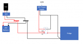
1) If you decide to do a relay only solution, use @time2roll suggestion of a double throw relay. It is simpler. (I show the circuit in post #7)
2) If you use the battery protect, the two high current diodes are required as shown in post 11. (I'll try to come up with something simpler... but right now this is the best I can think of.)
 
Thanks! Ordered parts that I have been sitting on my hiney waiting to purchase anyways - will have results to post in a few days.

Thanks everyone!
 
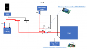
To be clear:

Normally closed is 24v Battery Power +
Normally open is 24v Power Supply +
COM1 is 24v Power Supply +
CH1/IN1 is 24v Power Supply -
 
No.

Normally closed is 24v Battery Power +
DC+ is 24v Power Supply +
Normally open is 24v Power Supply +
COM1 is fridge DC +
CH1/IN1 is 24v Power Supply -

See diagram.

1632094859988.png


Theory of operation.
1) When the 24V DC Power Supply is not supplying power, the relay module is off so COM is connected to NC and the Fridge is drawing power from the battery.
2) When the 24V DC Power Supply is supplying power, the relay module is on and the In1 signal is true so the Com is connected to NO and the fridge is drawing power from the 24V DC Power Supply.

Note: The Relay Module is rated for 30 A. I assume the fridge draws less than that.
Note 2A: There should be a fuse at the battery positive. The fuse should be 25% larger than the current drawn by the fridge or 25% larger than the current provided by the SCC. All wires from/to the battery should be able to handle the current the fuse is rated for.
Note 2B: There should be a fuse at the positive of the power supply. The fuse should be 25% greater than the current drawn by the fridge and all wires to/from the power supply should be able to handle the fuse rating.
 
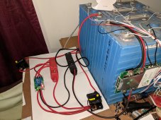
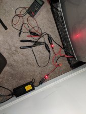
This is not the permament setup - I am going to clean it up tomorrow - this is a 'does it work' config.

And it does work!

Thanks!
 

Attachments

  • PXL_20211005_202013462.jpg
    PXL_20211005_202013462.jpg
    284.3 KB · Views: 10
  • PXL_20211005_202457593.jpg
    PXL_20211005_202457593.jpg
    217.3 KB · Views: 8
Back
Top