diy solar

diy solar

24v GROUNDING HELP and overall critique

Vinzent P

New Member
Joined
Sep 11, 2020
Messages
11
Grounding seems like an important issue for all us DIY'ers who are not electricians and start tinkering with electricity, and it has been the hardest thing for me to get a clear answer to, at least for these types of mobile setups.

I have assembled a 24v mobile system based on the blueprints here, along with help from the book (which I purchased), and of course the rest of the internet.

This is a large system for a large step van (an old FedEx truck) mobile home conversion, and I want the ability to power a mini-split ac unit, all the standard household stuff, power tools and light welder usage, so I went as large as I could afford.

Main components include:
(4) 370w solar panels
(4) LiFePO4 12v 138ah batteries
80a MPPT charge controller
3000w Inverter

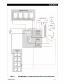
Attached is my diagram, which I am aware has some issues I will address below.

Now that I'm about to start electrical installation I am unclear on what to do about grounding. I have scoured the posts here and on other forums, tons of videos, and Will's book and can't find clear answers, at least that apply to my specific setup.

Yes, I have already watched all of the videos on the basics of circuits and grounding.

Yes, I have read the post with a similar title to this one, but still am unclear what to do since that setup is different.

Yes, I live in Florida with plenty of sun and plenty of lightning and intend to live in a large metal box.

Yes, I have read the manuals and NEC codes. Still confused.

I am NOT going to be charging off of the alternator and will NOT be using shore power. The system is intended to be completely separate from vehicle power.

The entire body and floor of the van is aluminum. The interior is insulated with polyiso board and spray, and is finished with wood paneling. All electrical components are mounted to a plywood board.

So here are my questions:
1. If grounded to the vehicle chassis, being that this system is 24v and the vehicle is 12v, will this difference in voltage lead to any issues?

2. Is there a difference in grounding to the chassis vs grounding to somewhere more convenient on the body?

3. If I do ground to the chassis, can the ground cable run off of the negative bus bar?

4. If the inverter and charge controller need to also be grounded as per their instructions, should those wires run back to the negative bus bar (which would run to the chassis), should they run to a close spot on the body of the vehicle, or should there be an entirely separate ground bus bar?

4. Do ground wires need to be solid wire, and what is the appropriate size for chassis, inverter, and charge controller wires?

5. Can/should the solar panel frames be grounded straight to the body somewhere on the roof?

6. Some people recommend not grounding to the vehicle chassis/body at all, citing the discrepancy between the vehicle's power and the sensitive components is a solar system. Is this insane and if not, how should protection be implemented?


Regarding my diagram, I realize that I may have over done it on some of the wire sizing since I sized for the surge of the inverter (6000w) vs it's continuous rating. I was also getting some conflicting info from different wire calculators, and of course every vanlifer has differing recommendations. Any help critiquing the wires and fuses of this system will be greatly appreciated.
I have spent a great deal of time trying to figure all this out, as even after years in fabrication and construction I'm still not an electrician. I'm not looking for a highly technical diatribe, I'm hoping someone out there has a similar setup and can say "do this and you're good to go," or that a bored electrician is wandering around this site and likes to explain stuff to adults as if they were 5 years old.

Thank you all, and thanks Will, this site is great.
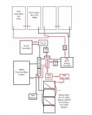
Wiring Diagram.jpg
 
When you say "ground" what do you mean? 120 volt mains have ground that is real earth ground. Vehicles do not, except when plugged into the ac mains. Then the green ground wires must connect back to the main service panel. The chassis should also connect to this green ground wire. It is life&death important that this green ground is continuous back to the mains service panel. My inverter has 12V positive and 12V negative. these connect to the appropriate battery posts, or buss bars. The inverter has a case lug. I connect that to the chassis. The negative buss bar connects to the chassis. Same thing with charging devices, battery charger and solar charge controller.
 
Quoting first response in a google search:
" Essentially, a "ground" is an electrical connection to a common return in circuit. In automotive terms a ground is a connection to the body or other metal surface of the vehicle. The body is connected to the negative terminal of the battery. "

I understand that in a car the path is not truly going into earth ground as it is in a brick and mortar set up. The car chassis and body are used to save on running negative wires to every component throughout the car as well a path for a short.

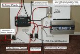
This image is the only one I can find on mobile-solarpower.com that actually shows a "ground" connection, but this set up involves a different setup that can charge from the vehicle alternator.
122-fgood_2_orig.jpg

No other diagram I can find on the site shows ground connections. On plenty of other DIY sites, wiring diagrams show "ground" connections, but they're not all consistent. Some show it direct from the battery or the negative bus bar, as well as the inverter and controller, but they don't all detail those connections and sizes, and none of them answer my question about "grounding" a 24v system to the 12v vehicle system.
 
I'm not a mobile solar guy but a Hot Rod Builder and motive tinkerer.

12V Chassis ground (negative) is for the whole vehicle, lights, electronics (think engine computer) and everything else. Many things pull that 12V (-) from a chassis contact. Most newer vehicles do not and actually have clean wired negative wiring for driving electronics now. Vehicles do not ground as they are mobile and on rubber, so quite isolated as rubber is a great non-conductor.

Generally, if someone is using 24/36/48V in a vehicle, they run a (+) & (-) for that current to whatever devices that use it, often via a small fused DC Panel as that really does simplify a lot of troublesome areas. Inverters that are "mobile-ready" will have a Bonding Circuit for such applications. ALWAYS Defer to the Equipment Manufacturers specifications & instructions in this regard, they do vary between makers.

Vehicle wiring should ALWAYS be stranded copper wire, never solid core ! (AC wire can be solid but if you look at a brand new RV and dig into the AC wiring, many are using stranded copper for AC as well due to movement & vibration which is not great for "hard-wire", it also adds cost in doing so.
Chassis to Frame Grounds are usually tinned copper braid stapping. TBH, If you secure your 14/ & 12/2 AC wire so that it won't move, vibrate or potentially wear against anything, it should be good.

We have do have some people here who I would classify as "expert" on vehicular systems.

Hope it helps a bit.
 
  • Like
Reactions: Dzl
Thanks for this info Steve_S, it's definitely informative even though I'm still left scratching my head for most of the details in my questions and wiring/fusing issues. Still researching...

Zil, it sounds like you recommend connecting neg bus bar to chassis, and inverter and controller ground to the body, although your system is 12v so I'm still unsure if that makes a difference. Thanks
 
With the disclaimer that I am still very intimidated by the complexities of vehicle grounding logic, have done a lot of research, but still consider myself ill-prepared and underinformed, (and in my experience most people do not adequately understand how grounding is applied in this context), my thoughts and answers to your questions are below (take them with a grain of salt):

I feel your pain, I've read and watched as much as I can, and still don't have a clear understanding, it doesn't help that most youtubers and DIY bloggers seem to avoid discussion of grounding (specific to vehicles or boats) like the plague, or talk about it piecemeal without really demonstrating or understanding the overall system or concepts.

1. If grounded to the vehicle chassis, being that this system is 24v and the vehicle is 12v, will this difference in voltage lead to any issues?
No difference in voltage. This is a fundamental component of grounding, a 'common ground reference' equalizes voltage. And because voltage is an 'across' variable measuring the difference between two points (+ and -) "12v" = +12v (red) and 0v (black) and "24v = +24v (red) and 0v (black). If the negatives (black) are both grounded (to chassis in this case), they share the same 'ground reference' and will be the same voltage relative to eachother and to chassis ground, while the positives will still be +24v and +12v. At least this is my best understanding (which--full disclosure--is extremely shaky at best). Search on youtube for "RSD academy Ground" for a better explanation that I can give.
2. Is there a difference in grounding to the chassis vs grounding to somewhere more convenient on the body?
All metal in a vehicle should be bonded. Most vehicles are all steel I think, since yours is Aluminum body, steel frame, it may be preferable to ground to one or the other. But in conceptual terms I believe 'chassis ground' encompasses both the body and the frame.
3. If I do ground to the chassis, can the ground cable run off of the negative bus bar?
I believe this is a common practice. Setting aside the BMS, grounding off the battery negative, or negative busbar, is conceptually the same.
4. If the inverter and charge controller need to also be grounded as per their instructions, should those wires run back to the negative bus bar (which would run to the chassis), should they run to a close spot on the body of the vehicle, or should there be an entirely separate ground bus bar?
I don't want to comment specifically on the Inverter, because that is very important and somewhat context based, the instructions in the user manual should be followed. As a general statement, "equipment ground conductors" wires connecting the (normally non-energized) metal equipment cases should be run back to the negative busbar (or a ground bus bar), then there should just be one connection from this to chassis-ground. At least that is my developing understanding.
4. Do ground wires need to be solid wire, and what is the appropriate size for chassis, inverter, and charge controller wires?
All wire in a vehicle or boat should be stranded. Ground included.
The second part of you question can/should be answered by whatever code is applicable and device documentation. When in doubt, use the same size or larger wiring as you used for + and -. At least that is how I would approach it. But mostly, check the code (relevant sections of NEC and ABYC (marine code which is more human readable and DIY friendly) are uploaded in the resources section.

5. Can/should the solar panel frames be grounded straight to the body somewhere on the roof?
Not sure.
6. Some people recommend not grounding to the vehicle chassis/body at all, citing the discrepancy between the vehicle's power and the sensitive components is a solar system. Is this insane and if not, how should protection be implemented?
I have heard okay reasons for not grounding, none have been related to the 'sensitive' components of a PV system though. I would think that modern vehicle electronics are as sensitive or more sensitive than off-grid PV components, but this is pure speculation. A general piece of advice I've heard is that grounding your vehicle's 'house bank' to chassis should be the default approach unless you have a specific reason not to.

One more point, in terms of inverters, for vehicles (where shorepower will be utilized sometimes) a UL 458 rated inverter should be used (or at least one that complies with the standard regardless of whether it is actually certified).
 
Last edited:
Some useful resources for info on grounding
Victron Wiring Unlimited (resources section of this site)
RSD Academy (youtube)
Samlex Evo manual (even if you don't have this inverter)
Magnum MS manual (even if you don't have this inverter)
ABYC Code (resources section of this site)
Mike Holt (youtube, not vehicle specific, but lots of info to be absorbed from his lectures and rants--he teaches NEC code)

Search this forum for my username + ground, I have very few answers, but have asked lots of questions and got some good feedback and posted various resources.

When searching google, its easier to find high quality marine resources than vehicle based resources, and there is a lot in common between the two applications, so use keywords that will help with that.
 
Last edited:
Well Dzl, with grain of salt taken, your replies are VERY much appreciated, thank you! ?‍♂️
This definitely helps get me closer finalizing the method I was leaning towards.

Those resources are great, I had not come across RSD Academy. I love the classroom style explanations.

I did notice the abundance of info online for marine applications, which is informative and helpful, but still nothing that directly compared to this set up.

Thanks again for your time and input!
 
  • Like
Reactions: Dzl
From wikipedia the first sentence "In electrical engineering, ground or earth is the reference point in an electrical circuit from which voltages are measured, a common return path for electric current, or a direct physical connection to the earth." -- https://en.wikipedia.org/wiki/Ground_(electricity)

I'm sure my understanding is imcomplete and possibly just wrong, my goal is to foster discussion and provoke somebody who knows this better to hit me upside the head with the clue bat.

When people talk about ground in the automotive sense they are likely talking about the common return path.
Electricity flows to its polar opposite so as long as one side of the circuit is isolated the other side can be shared.
By convention if one side will be shared its the negative side.

The other concept is "reference".
Airplanes adjust their altimeters with reference to sea level.
Voltage is similarly relative.

WARNING: This final part is murky at best, for me anyways.
Electricity doesn't just exist in your system its everywhere all the time.
We connect our systems to the earth as its the most common electrical reference that is practical.
Since complete isolation is impractical we use the planet as a "lost and found" for induced currents.
Pretty sure the analogy is weak but its the best I could come up in the moment.
 
Last edited:
Zil, it sounds like you recommend connecting neg bus bar to chassis, and inverter and controller ground to the body, although your system is 12v so I'm still unsure if that makes a difference. Thanks
It does not matter if there are different dc voltage supplies negative's connected to same chassis. The electrons are very smart. they will only go back to where they are from. Actually electrons don't go very far at all, but it gets to complicated to explain, so only some old guy at the university talks that way.
 
Looking at your diagram, you need to move the positive feed off your bank to the other battery, or the negative feed to the other battery.
 
If your roof is aluminum your solar panel frames will already be grounded to roof when you mount them so no need to ground frames
 
Thanks for the input guys.

Instead of the negative bus bar I'm going to connect a battery negative to the chassis since I have just enough cable for that distance. I'll ground the inverter and charge controller to the aluminum wall behind the wooden panel board via through bolt.

As far as the roof - the panels are actually attached by plastic brackets with vhb tape and silicone caulking, the same kind Will Prowse recommended on the site. I was skeptical of this connection at first but was convinced by many other who have had success with it that it's a much better idea than drilling what would have been at least 24 holes in my roof. I've worked with many types of vhb and when used on a clean surface the stuff is amazing. They've been attached for weeks now and after a few hundred miles they haven't budged. Still, I did put three stainless steel brackets at the front which are through bolted, and have two runs of stainless aircraft cable attached to them going through all of the panels as safety lines. Those brackets now act as a ground connection for the panel frames to the body.

As far as my battery configuration, Electric Personality - maybe I'm wrong but I'm not seeing the discrepancy. My batteries are stacked vertically in a 1S1P arrangement. Looking at the example on this site attached below, if you take the two sets of batteries, stack them, and swap which side the pos and neg poles are on, it is the same config. If I'm missing something please reiterate.

ecsefes_1.jpg
 
Thanks for the input guys.

Instead of the negative bus bar I'm going to connect a battery negative to the chassis since I have just enough cable for that distance. I'll ground the inverter and charge controller to the aluminum wall behind the wooden panel board via through bolt.

As far as the roof - the panels are actually attached by plastic brackets with vhb tape and silicone caulking, the same kind Will Prowse recommended on the site. I was skeptical of this connection at first but was convinced by many other who have had success with it that it's a much better idea than drilling what would have been at least 24 holes in my roof. I've worked with many types of vhb and when used on a clean surface the stuff is amazing. They've been attached for weeks now and after a few hundred miles they haven't budged. Still, I did put three stainless steel brackets at the front which are through bolted, and have two runs of stainless aircraft cable attached to them going through all of the panels as safety lines. Those brackets now act as a ground connection for the panel frames to the body.

As far as my battery configuration, Electric Personality - maybe I'm wrong but I'm not seeing the discrepancy. My batteries are stacked vertically in a 1S1P arrangement. Looking at the example on this site attached below, if you take the two sets of batteries, stack them, and swap which side the pos and neg poles are on, it is the same config. If I'm missing something please reiterate.

View attachment 22571

What do you mean by ground the inverter and the charger controller to the aluminum wall instead of a negative busbar?

If you just mean connect the equipment ground points (metal chassis') of the equipment to the aluminum body of the vehicle, that might be fine. But it is not recommended to use the chassis or body of the vehicle as your negative wiring if that is what you mean. Vehicle electrical systems do this to cut costs, because they are relatively low power systems, but its not reccomended to do this for your house bank wiring, particularly with high current devices like an inverter (at least that is my understanding).
 
Sorry maybe that was worded poorly.

I have just enough 2/0 cable left to make a ground connection from the negative terminal on the lowest battery to the vehicle chassis. I don't have enough to go from the negative bus bar as originally planned, but running from the battery negative terminal is the same, correct?

Correct me if I'm wrong here, and this relates to my original questions: The inverter and the charge controller both call to be grounded, in this case, to vehicle chassis, and have terminals labeled for this. Since the wall I'm referring to is bare aluminum, bolted to bare aluminum floor, which is bolted to the steel chassis, isn't bolting the ground wires from the inverter and controller to this wall equivalent to connecting them to a negative bus bar, or a ground bus bar, either of which are then grounded to the vehicle chassis?

I'm noticing how easy is can be mix up the chassis of the component with the chassis of the vehicle when writing about this.

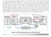
Below is a diagram from the controller manual (Outback Flexmax 80), and text from the inverter manual (Giandel PS-3000KAR):
outback-power-systems-flexmax-80-owners-manual-page15.pngInkedScreenshot (5)_LI1.jpg
 
I have just enough 2/0 cable left to make a ground connection from the negative terminal on the lowest battery to the vehicle chassis. I don't have enough to go from the negative bus bar as originally planned, but running from the battery negative terminal is the same, correct?

Correct, or at least to the best of my knowledge that is correct, until you put things between the battery negative and negative busbar that could disconnect (like a FET based BMS) then its a slightly more complicated situation which I don't have a full understanding of.

Correct me if I'm wrong here, and this relates to my original questions: The inverter and the charge controller both call to be grounded, in this case, to vehicle chassis, and have terminals labeled for this.

Correct so far.

Since the wall I'm referring to is bare aluminum, bolted to bare aluminum floor, which is bolted to the steel chassis, isn't bolting the ground wires from the inverter and controller to this wall equivalent to connecting them to a negative bus bar, or a ground bus bar, either of which are then grounded to the vehicle chassis?

Kindof yes. To the best of my limited understanding, these two situations you lay out are conceptually similar, with some differences. I think there are 2 reasons it is recommended to run your equipment ground wires back to a common busbar (as in the Outback schematic), and then ground that to the vehicle chassis. First, to prevent possible ground loops. Second, to minimize the points where dissimilar metals meet and corrosion can occur. I'm not 100% sure I understand all this correctly, but that is my current understanding.

The Outback Flexmax picture you posted above is a good representation what I understand the best practice for DC grounding to be.

I'm noticing how easy is can be mix up the chassis of the component with the chassis of the vehicle when writing about this.

The language (at least the langauge us lay-folk use) to talk about grounding is imperfect at best and can be very confusing. This post has some good info and good formal terminology
 
Ah yeah! I remember now reading about having only one ground to vehicle chassis point to avoid ground loops (which I haven't gotten around to understanding), so grounding the inverter and controller at other separate places would break that rule.

Hence the ground bus bar in the controller diagram, yes.

Other than for better organization, is there a reason to have a dedicated ground bus bar since it is directly connected to the negative bus bar? Without it could the inverter and controller ground wires would be run back to the negative bus bar, which their negative wires are already attached to?
 
Ah yeah! I remember now reading about having only one ground to vehicle chassis point to avoid ground loops (which I haven't gotten around to understanding), so grounding the inverter and controller at other separate places would break that rule.

I haven't either, beyond that they are something you want to avoid, and have to do with current potentially flowing in ways you don't want it to.

Hence the ground bus bar in the controller diagram, yes.

Other than for better organization, is there a reason to have a dedicated ground bus bar since it is directly connected to the negative bus bar? Without it could the inverter and controller ground wires would be run back to the negative bus bar, which their negative wires are already attached to?

Not postive, but I'm pretty sure, whether you use a dedicated ground bus, or just a negative bus for both negative and ground connections the result is the same, I think the main purpose is clarity, tidyness. My guess is that a dedicated ground bus becomes more meaningful with larger, more complex systems, but for our simple systems its probably not necessary to have separate buses. This is something I should probably look into, since I really don't know.
 
Last edited:
Dzl - I think some info from RandyP in the link in your previous post answers the question:

1586378034347.png


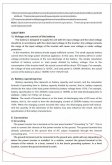
Looking back through my controller manual it also calls to keep negative and ground connections separate, if this is referring to the same thing:

Screenshot (7).png
 
Ok...

“ground” means SOOOOO many things...

I try to use “bond” instead, as it is less confusing. bonding metal parts to provide a fault path. Allows damaged systems to trip breakers. Needs to be unbroken continuous path to current source.

ground or earthing also is for atmospheric dissipation of static, and lightning...

Vehicle batteries get “grounded” to chassis because wire is expensive, and the chassis is there anyway. On an inverter bank battery, unless you use the chassis for device current path, I don’t see the need for grounding it... and it could create a dangerous shock hazard with voltages above 24V...

The inverter chassis if they have ground points, they must be grounded to chassis, and IF ANY APPLIANCES ARE POWERED OUTSIDE THE VEHICLE the chassis must be grounded to earth.

That means if you plug a cord into the vehicle mounted inverter, and power stuff outside the vehicle like lights, radio, tv, fans, power tools, what have you, you can be standing on the earth and be electrocuted if something goes wrong.

remember, the marine codes don’t take this aspect into consideration much... water IS EARTHED, and it’s hard to avoid that path... RV... not so much.
 
Back
Top