diy solar

diy solar

25kWh daily output, but I only used to need 10kWh per day.

The batteries ran out of power overnight because I had set the dishwasher to start running at 4 o'clock in the morning - normally I wouldn't turn it on until around 11-12 the next day, but I've got so used to using the grid power for the past three days that I forgot.

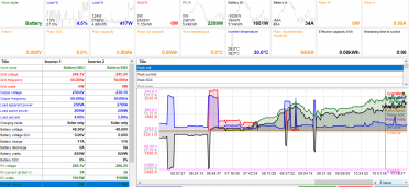
I've attached today's MultiSIBControl screenshots. These were the battery readings:
9:30 46.7V SOC 7%
10:00 46.9V SOC 6%
10:30 47.2V SOC 6%
11:00 47.6V SOC 7%
11:30 48.6V SOC 9%
1.14kWh had gone into the batteries by 11:30, according to the screenshot.
Now, at 11:55am, 2.05kWh have gone into the batteries, and the SOC is up to 14%.
(I live on a hill with woods to the East, and the sun doesn't get above the trees until gone 10:30 in October.)

I will do some voltage readings from the battery terminals with my multimeter and post them up tonight, after it's fully charged.
Mattb4, I think I need to get two more batteries to get me through the night with plenty to spare. Peak loading hasn't been a problem, I went with 2 x 5kW inverters because the maximum I never need is one 4.5kW shower and two 2kW bathroom fan heaters on at the same time, plus 0.5kW for the background stuff that might be running (fridge, freezers (3), lights and computer.) There aren't any periods of high daily use that I'm aware of, since I got into the solar panels I have been religiously watching every appliance I use, and looking at the graphs on MultiSIBControl.
 

Attachments

  • 17-10-2022 Batteries very slow charging.PNG
    17-10-2022 Batteries very slow charging.PNG
    104.6 KB · Views: 6
  • 17-10-2022 Batteries very slow charging.PNG
    17-10-2022 Batteries very slow charging.PNG
    104.6 KB · Views: 6
I emailed the developer of MultiSIBControl and asked him about my problems - he said that each inverter will use around 2kWh per day, so that's at least 4kWh of my 25kWh gone, plus the numerous losses during conversion from PV to battery, from PV to 240V house load, and from battery to 240V house load. He also said that he doesn't use the communication cable and doesn't connect his batteries to his inverter, he uses 'USR' in Program 6, and recommends the following settings:
Bulk charge: 52.5V
Bulk float charge: 52.2V
Battery low cut off: 45.3V

I have changed my settings to these and everything seems to be working okay, except that MultiSIBControl now reports that my full batteries (going by the LEDs on the batteries) only have 57% SOC. I don't know if that will change over the coming days as the inverter 'gets used' to the new voltage settings?
 
I may have missed something but when you programmed the MPP unit there is a selection screen that allows you to program priorities like where your power comes from first. From memory you have options like SBU (solar first, then battery if solar isn’t sufficient, then lastly AC in) or the other combinations. Have you chosen the correct one? You need to be SBU, NOT BSU or any other option, just a thought.
 
have changed my settings to these and everything seems to be working okay, except that MultiSIBControl now reports that my full batteries (going by the LEDs on the batteries) only have 57% SOC.
Probably even less, at those settings.
Not getting close to a full charge.

Edit: this is if you are using LiFePo4 batteries.
I was assuming you were.
 
Brianonmull, I have got the settings as SBU, thanks for the suggestion. timselectric, I have set the battery setting (I think it's no. 5) to 'PYL', I now understand why the lower voltage will only charge the battery so far and then not be high enough to go any further, as the batteries' voltage will have increased sufficiently to need a higher voltage coming from the inverter. Unfortunately it's pouring with rain today so PV output isn't great, but hopefully this will fix the problem.
(I am using LiFePo4 batteries, three Pylontech US5000s.)
 
Hi, l’m just about to do the same as you and I am hoping not to run in to the same issues that you have. Currently use a PIP 5048MGX with a repurposed Nissan Leaf battery and have used my custom settings under USR for the past couple of years without any charging issues and the PIP has charged and discharged to those limits perfectly as it needs to as I don’t run a BMS. However I have just taken the plunge and gone for a PIP6048MT and 4 Pylon US5000s. Did you make a custom BMS cable or one from MPP? I have read about cable issues between the two, but as you state it is only a 2 wire interlink. Using PYL setting on the PIP seems to me to indicate that communication between the two is a little more sparse in terms of setting limits. Whereas if you match a US5000 with a Victron Multiplus for example you don’t need to make any setting, just seems like the cable shares a lot more. I’m going to be keeping a close eye on things to start with. I’m not sure I understand all your issues, but are you in a better place now re SOC. Brian
 
Hi Brianonmull, I received a custom Pylontech cable with the MPP Solar inverters - the end marked 'Pylon' has to go into the master battery's RS485 port (you could easily just think that the 'Pylon' sticker just tells MPP Solar that it's a Pylontech cable, and put either end into the battery - but it only works one way round, as the pins that are actually wired are different at each end.)
Re the communication between the two - I have no idea how much data is actually going into the inverter from the batteries, but using the same RS485 port on the battery, and MultiSIBControl, you get lots more data than the inverter would ever need (I think). Have a look at multisibcontrol.net to see.
Can you tell me - when you set your PIP5048MGX to 'PYL' in setting 5, does setting 2 limit you to 20A? I've only just noticed it, as for the past three or four weeks, I've been using the 'USR' setting, and I manually set setting 26, 27 and 29 myself, according to what the developer of MultiSIBControl told me, and I'm pretty sure I had setting 2 at 80A, which is what the Pylontech manual recommends. While I was changing setting 5 to 'PYL' today, I decided to increase setting 11 (utility charging current amount for the battery charging) from 2A to 20A, and I noticed that in Solar Assistant, it said setting 2 was 120A, and when I tried to change it to 80A, it just changed it back to 120A (this is in Solar Assistant, on the inverter it said 20A). All very confusing and misleading.
The temperature of my three batteries is 11-12C today, and I think it's been that way for a week or more, I haven't really paid it much attention - I wonder if the charging current for the batteries in setting 2 is limited by the inverter to 20A if the batteries are below a certain temperature? Otherwise, I can't understand why the inverter's 'PYL' setting has forced setting 2 to 20A. I could easily just change setting 5 to 'USR', set 26, 27 and 29 with whatever the 'PYL' settings are, and then manually adjust setting 2 back to 80A I suppose, but I only got 9kWh of PV today, my worst ever, so it wouldn't have made much difference.

One thing I can confirm is that, using a clamp meter, 15A was going through all of the inverter to battery cables, when I had finished changing these settings today (I wanted the grid to charge the batteries continuously until they were fully charged, since the PV was so bad today, so I set setting 1 to USB, (utility first and only use solar or battery if the utility fails) - but it only charged the batteries at 15A for about twenty minutes, and then stopped charging them. They were at about 12% SOC, according to MultiSIBControl.
I presume the inverters will only supply charge to the batteries from the grid until they reach a certain SOC, which is quite low?
 
Hi, (where are you by the way?). From experience with the MGX, when I connect the utility to the unit and you are running under ’USB’ the unit just charges away, never stopping until it reaches my programmed presets under USR. So in my case it will try to get to 56.4v, (lithium ion - Leaf cells). The speed at which it charges depends on the programmed settings which is a mix of utility charger and PV charger that you set. I my case the utility charger I think I only set to 20A, so less than a 1000w, but that suits me, but have you set yours appropriately? But from memory there are other settings that can impact utility charging further down in the menus?
What about charging the batteries from solar or grid with the Pylontech BMS cable unhooked? If you have put the Pylon settings in under USR, then I doubt that there could be any downside for a test and try to get the battery SOC right up. The battery units have inbuilt BMSs, so regardless of the cable they would disconnect from the charge if they did see something abnormal. Nothing to lose.
 
when I turn on a 2kW heater, I see a 2kW increase in the graph of the PV, and I've had multiple loads on at the same time - a kettle, (2kW), a bathroom heater (2kW) and an immersion heater (3kW), and the PV graph rose by 7kW to match it.
This indicates to me that your battery charging settings are limiting input- doesn’t address your issue but an observation, like you are set up SUB
Or your unit may be intentionally throttling the panels to limit power sent to the battery, and the higher power levels with the heater on resets the logic that decides battery charging rate
Sortof- see above.
 
I am now set up as USB, as all I want to do at the moment is see if I can get the batteries to fully charge. I will change setting 5 from 'PYL' to 'USR', then replicate the 'PYL' voltage settings in 26, 27 and 29, and change setting 2 (maximum charging current from utility and solar combined) to 80A, and setting 11 (Maximum utility charging current) to 60A.
I've just looked at the manual, and I think I need to just change setting 16 (solar energy priority) to either Sbl UCb (Solar energy for battery first, allow utility to charge battery (default)), or Slb Ucb (Solar energy for load first, allow utility to charge battery). I have always had it set on Slb UdC (Solar energy for load first, disallow utility to charge battery) - I think that is the later setting that you refer to, brainonmull. I will remove the Pylontech to inverter lead as well.
 
I've set the inverter to Sbl UCb, and changed setting 11 to 60A, the fans immediately sped up and the inverter display says that 60A is going into the batteries, but when I test the battery cables with my clamp meter, it only shows 45A. I changed setting 11 to 20A, and my clamp meter shows 15A in the battery cables. I've left it at 20A because it's late now, and I can let it charge overnight. Hopefully by the morning all three batteries will be completely charged. (I bought a third Pylontech US5000 which arrived last week.)
 
Last edited:
This morning, the two older batteries were completely charged (all 6 LEDs lit up), but the new battery's alarm was going off (it's the new master battery) and after I turned everything off and on again, only 2 of its LEDS were lit. So I'm pleased that the two older batteries have completely charged up, but now I think I need to try equalizing the batteries? Or I could unplug the two older batteries, and just leave the new one plugged in and charge it right up from solar today. Which will probably be easier to do than trying equalizing? Then I could try equalizing them when they are all completely charged?
 
just leave the new one plugged in and charge it right up from solar today.
Provided all else is well that is what I would do.

Equalize is for flooded lead acid and while voltage dependent is less about voltage than about electrolyte and plate maintenance
 
According to the Pylon manual or videos I have seen, you can add batteries at any time to an existing stack. They are unlikely to all be at the same state of charge but what you should do is connect them all together and in a short time they should balance themselves out. If you have two full ones and one part charged if you do this you should be able to see current moving from the charged ones to the less charged one using a clamp meter. Should initially be quite a surge, but slows down quite quickly until they are balance With these batteries voltage is sometimes misleading as the charge curve is very flat with maybe less than 0.3v being the difference between 60% charged and 95%.
 
Thank you all for your replies - this morning, all three batteries were showing approximately the same SOC in MultiSIBControl. Later this afternoon, all three batteries had four solid LEDs out of six, and MultiSIBControl was showing they were approximately two thirds full, so that's good.
One strange thing is that when I change Setting 5 to 'PYL', Setting 2 shows 20A, and if I try to change it, when I go into the settings again, it's changed itself back to 20A. An hour or so later, it now said 40A. Does anybody else with an MPP Solar (or clone) inverter have the same settings? My max PV today was 5393W, so I want to get a lot more than 20A going into the batteries per inverter.
I will do what I said I should do, three posts up - "I will change setting 5 from 'PYL' to 'USR', then replicate the 'PYL' voltage settings in 26, 27 and 29, and change setting 2 (maximum charging current from utility and solar combined) to 80A,".
But thank you so much to timselectric for your post! Your advice is what's fixed it all for me.
 
I still have a problem: my inverters are showing 17A to 19A going into the batteries, but when I use my clamp meter, it initially only showed 6A going through the battery cables, then ten minutes later it only showed 3A! My PV is currently outputting over 2kW, that's what I normally get all day long on a cloudy day from my 12kW of solar panels, so I know the power is coming into the inverters. If I turn on a 2kW kettle, I see the grid kick in but I can tell by the speed of the meter wheel (I have a VERY old meter) that it's only 500w or thereabouts coming off the grid, which agrees with what MultiSIBControl shows me. But for some reason, the Pylontech batteries aren't accepting most of the current that the inverters are trying to charge them with. They only have 1 LED lit each. I am using the 'PYL' setting in Setting 5 of the inverter, so the charge voltage is 53.2V.
I would imagine there must be tens of thousands of MPP Solar/Axpert/Victron inverter owners who are using Pylontech batteries, does anybody else use these and know what I should try to fix it?
 
Isn’t 53.2 a bit low - like a float voltage- for a 48V system? But I know nothing to little, it just seems 56.x VDC is more commonly mentioned. For LiFePo
 
53.2V is the charge voltage that the MPP Solar PIP5048MKX inverter automatically sets when you select 'PYL' in setting 5, and the Pylontech manual says 'Charge Voltage: 52.5-53.5'. The current voltage of the batteries is 48V, I don't know if that would make a difference.
I am back with the same problem I had when I started this thread - however much my PV makes and the inverter says is going into the batteries, the batteries are only taking a third to a half of it.
 
First off the Pylons are not like some other LiFePO4 units they are a 15S design, so the maximum theoretical charge they should be maxed at is 15x3.65=54.75v - but don’t go there it’s not necessary. LiFePO4 are 95-98% charged at 3.45v, no point stressing the battery above that point. Victron who also support Pylon batteries state that often the 53.2/3.55v per cell is often found to be too high and they report that cells thus charged are inclined to go over voltage and cause other alarms. The Victron reccomendation is to go for 51.8v (3.45v per cell) for the ‘bulk’, and 51v, (3.4v per cell) for ‘absorption’, and ‘float’ at 49.7v, just a tiny bit lower, (you don’t really float lithium).
Victron also note that the batteries can be quite difficult when new as sometimes they don’t charge/balance very well. Their advice is to ’fix’ a lower charge voltage, 51v.
Other advice is really to fully charge each US unit before you put the on a syste, (I purchased a small 15S LiFePO4 charger off EBay, 20a/51.8v, I think for around £60), used that to charge my 4 US5000s, then hooked them together in 2s to balance and then 4 together to hopefully finally balance the whole pack.
Personally to see if you can get full charge into your units on the PIP, I’d try and get them as balanced as possible first, disconnect the BMS cable, manually set the parameters like Victron suggest and use the grid to charge the unit so that it is getting a constant current, unlike relying on the sun going in and out as the PV side is likely to do. Keep an eye on the voltages, but no harm will come as the BMSs are still active inside the units. See how it goes? Also make sure your batteries are somewhere quite cosy as they derate very quickly as they get colder.
 
Thanks for your advice, Brianonmull, I am trying it right now (51.8V bulk, 49.7V float) - but look at Timselectric's post higher up this page, he said that my using
Bulk charge: 52.5V
Bulk float charge: 52.2V
Battery low cut off: 45.3V
(recommended by the developer of MultiSIBControl)
wouldn't come close to fully charging the batteries.
I can see that if the voltage was too high for the batteries then they would restrict the amps they will accept from the inverters, thus I am seeing much lower amps in the battery cables, using my clamp meter, than the inverters say they are sending to the batteries.
I will just use the inverter's 20A setting to charge the batteries now and see if it works, and I will also take meter readings to see how many kWh it actually took from the grid during this time.
I have no absorption setting on my PIP5048MKX inverters, only setting 26 (Bulk charging voltage) and setting 27 (floating charge voltage).

ps when you mentioned derating as they get colder - how cold? Mine have been at 12C for the past few weeks, they are 14C today.
 
Back
Top