Dear all, I am looking for some kind advice I guess. I was running my hybrid system by using 1x Growatt SPF5000ES and experiencing a few overloads because load peaking above 5kwh. Otherwise no issues to report. So I got a second SPF5000ES and installed them in parallel mode. Today. All works fine as long as the inverters pull energy from the battery e.g. SBU output mode. Once I switched the Master unit to SUB (or SOL) in the evening (therefore asking to move to utility/grid), the utility master breaker (being the one of the utility provider) opens and inverters go back to battery. So I basically cannot use grid energy anymore. Is there anyone able to shed some light here please? Many thanks indeed.


You are using an out of date browser. It may not display this or other websites correctly.
You should upgrade or use an alternative browser.
You should upgrade or use an alternative browser.
2x Growatt SPF5000ES in parallel mode. Grid master breaker opens.
- Thread starter Elian
- Start date
FilterGuy
Solar Engineering Consultant - EG4 and Consumers
Is it an RCD or regular breaker that is poping?Dear all, I am looking for some kind advice I guess. I was running my hybrid system by using 1x Growatt SPF5000ES and experiencing a few overloads because load peaking above 5kwh. Otherwise no issues to report. So I got a second SPF5000ES and installed them in parallel mode. Today. All works fine as long as the inverters pull energy from the battery e.g. SBU output mode. Once I switched the Master unit to SUB (or SOL) in the evening (therefore asking to move to utility/grid), the utility master breaker (being the one of the utility provider) opens and inverters go back to battery. So I basically cannot use grid energy anymore. Is there anyone able to shed some light here please? Many thanks indeed.
FilterGuy
Solar Engineering Consultant - EG4 and Consumers
Hmm. OK. Do you have a diagram of the system?
Quattrohead
Solar Wizard
Sounds to me like you might have the phases back to front on one of them compared to the other.
FilterGuy
Solar Engineering Consultant - EG4 and Consumers
I was wondering the same thing.Sounds to me like you might have the phases back to front on one of them compared to the other.
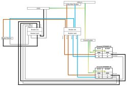
Hope this makes any sense. Again, the 2x inverters are connected in parallel by the means of 2+2 connection cables provided by the manufacturer.Hmm. OK. Do you have a diagram of the system?
Attachments
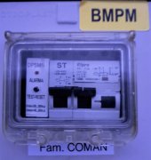
This is a picture of the breaker.Is it an RCD or regular breaker that is poping?
Attachments
FilterGuy
Solar Engineering Consultant - EG4 and Consumers
I could not find a spec sheet for that breaker but I looke up EN 61009-1 and as I suspected, it is a residual current breaker (with over-current protection).This is a picture of the breaker.
What we don't know is if the breaker tripped due to ground current or due to overcurrent.
FilterGuy
Solar Engineering Consultant - EG4 and Consumers
I am struggling to understand all the different breakers.Hope this makes any sense. Again, the 2x inverters are connected in parallel by the means of 2+2 connection cables provided by the manufacturer.

I am particularly confused by the breakers on the left. It looks like it is some kind of transfer switch between the grid and the inverter. Could we ge any more detail on what they are and how they are wired?
EastTexCowboy
Solar Wizard
Looking at the SPF5000ES specs it seems to me that a 32A breaker is insufficient.

I agree with @FilterGuy about the diagram with all the breakers is a bit confusing.
I agree with @FilterGuy about the diagram with all the breakers is a bit confusing.
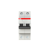
So all the 3 breakers are something like the one attached (25A btw). The one to the right (in the diagram) is for utility/grid coming in and out to inverters, both L and N. The breaker in the center is for collecting inverters output and taking it to the loads. These are meant to work together, both closed (current goes through - inverters work) or open (current does not go through, inverters are isolated). The breaker to the left is a bypass - it is always open when the other two are closed; if / when inverters are off duty (e.g. they are tripping the utility master breaker - the very case here) I can engage the breaker and the house (loads) is powered by utility directly. Hope this sheds some light.I am struggling to understand all the different breakers.
View attachment 133574
I am particularly confused by the breakers on the left. It looks like it is some kind of transfer switch between the grid and the inverter. Could we ge any more detail on what they are and how they are wired?
Attachments
Hedges
I See Electromagnetic Fields!
- Joined
- Mar 28, 2020
- Messages
- 20,530
I could not find a spec sheet for that breaker but I looke up EN 61009-1 and as I suspected, it is a residual current breaker (with over-current protection).
What we don't know is if the breaker tripped due to ground current or due to overcurrent.
Does the added inverter have a neutral-ground bond? That is active while grid feeds, or bonds while off-grid and doesn't open fast enough to beat the RCB tripping?
However the spec from Growatt is hard to meet. 100A breaker on the utility inbound is not something I can accommodate nor the supplier - this is 22kwh... Meanwhile I have made a test - wired the inverters chassis together and to the grounds wire. It worked fine for like 5-10 minutes and then, while switching from an AC output mode to another (eg. SBU to SUB), the utility master breaker tripped again. So for the time being I have switched back to my initial setup (1x inverter only) and everything goes well. I really suspect my grounding is not adequate and creating the problem. The journey continues I guess.Looking at the SPF5000ES specs it seems to me that a 32A breaker is insufficient.
View attachment 133578
I agree with @FilterGuy about the diagram with all the breakers is a bit confusing.
FilterGuy
Solar Engineering Consultant - EG4 and Consumers
So all the 3 breakers are something like the one attached (25A btw). The one to the right (in the diagram) is for utility/grid coming in and out to inverters, both L and N. The breaker in the center is for collecting inverters output and taking it to the loads. These are meant to work together, both closed (current goes through - inverters work) or open (current does not go through, inverters are isolated). The breaker to the left is a bypass - it is always open when the other two are closed; if / when inverters are off duty (e.g. they are tripping the utility master breaker - the very case here) I can engage the breaker and the house (loads) is powered by utility directly. Hope this sheds some light.
I think I *might* understand.
Is there any type of interlock that prevents the bypass breaker from being on at the same time as the middle breaker that goes to the load? Is it possible to accidentally have them both on at the same time?The breaker to the left is a bypass - it is always open when the other two are closed;
FilterGuy
Solar Engineering Consultant - EG4 and Consumers
It sounds like it tripped when transitioning from grid to battery power.while switching from an AC output mode to another (eg. SBU to SUB), the utility master breaker tripped again.
Does the added inverter have a neutral-ground bond? That is active while grid feeds, or bonds while off-grid and doesn't open fast enough to beat the RCB tripping?
I think @Hedges is on the right track. It may be due to multiple N-G bonds if both inverters have the bonding screw.
Not at this stage so technically there is such a risk / possibility. However the breakers are in separate boxes and the bypass box is locked and secured. I plan installing a switch to make things error proof.I think I *might* understand.
Is there any type of interlock that prevents the bypass breaker from being on at the same time as the middle breaker that goes to the load? Is it possible to accidentally have them both on at the same time?
Florin Radu
New Member
- Joined
- Nov 6, 2022
- Messages
- 5
If only the RCD decouples (32a) and no other "downstream" classic breaker (25a), is it possible that improper or missing ground to generate such an issue?
Hedges
I See Electromagnetic Fields!
- Joined
- Mar 28, 2020
- Messages
- 20,530
I think @Hedges is on the right track. It may be due to multiple N-G bonds if both inverters have the bonding screw.
One vs. two wouldn't matter to RCB. Except, if one connects to grid while other provides line/neutral bond.
A single inverter *might* disconnect the bond with timing that doesn't cause RCB to see ground leakage. Two inverters might be timed differently.
I don't think bond in just one of two inverters would prevent this. Either switching onto or off grid, there could still be a case where one provides the bond and the other connects to grid.
If this is the issue, disabling neutral/ground bond in both inverters and connecting neutral in to neutral out could work.
Of course, any leakage to ground can trip RCB. Too many EMI filters (imbalanced between L1 and L2) can do that.
Try the switching with no loads, light loads, heavy loads. To separate RCB trip from over-current trip.
Of course, the idea that connecting to grid shorts the phases should be investigated. Try inverters connected to RCB and grid, but output Line and Neutral disconnected.
Florin Radu
New Member
- Joined
- Nov 6, 2022
- Messages
- 5
I've spotted a recent topic on the same challenges --> https://diysolarforum.com/threads/m...upstream-rcbo-when-working-in-parallel.54728/
Similar threads
- Replies
- 1
- Views
- 273
- Replies
- 2
- Views
- 358
- Replies
- 10
- Views
- 510
- Replies
- 6
- Views
- 621