2TrevorJ
Bend the Joules
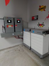
After 1-1/2 years of planning I'm roughly a week and half into my new setup. 2x15Ks - 57.6 kWh of HomeGrid Stacks - 20.4 kW of REC's w/ Tigo TS4-A-O Optimizers and Cloud Connect Advanced (CCA) - Bypass/Transfer Switch - MicroAir Easystarts on my 3.5 & 4-ton AC units. Big house draws are pretty much all gas (other than the oven and my daughter's Nissan Leaf) so I have quite a bit of power to spare right now, but July & August should be close if my math holds out. So far this has handled everything I've thrown at it with zero compromises. There's actually a screen shot from this morning with me charging the batteries, the car, and exporting all at once. ? The only disappointment so far has been the lack of 600A charge limit from the Homegrids when they prominently advertise 300A for each stack. Most of the time the BMS is calling for 200-240A (total). Super conservative at <= 0.2C. That said, I've barely ever run into the charge limit and started exporting on PV. I was at 100% yesterday at 17:15, 79% at dawn this morning, and was topped back off and exporting by 10:40. ? Now, before anyone mentions it...yes this was an expensive endeavor that doesn't make a whole lot of sense if all you're after is ROI. That's not my focus. Feel free to ask any questions about the system/performance/behavior.
Attachments
-
 Setup.JPG89.1 KB · Views: 360
 -
 Charging Batts Car and Exporting2.gif15.9 KB · Views: 338
 -
 Max Charge3.gif50.9 KB · Views: 255
 -
 Max Prod2.gif54.4 KB · Views: 243
 -
 Full Day 2.gif27.2 KB · Views: 301
 -
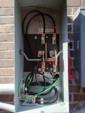
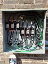 Distro Blocks.JPG214 KB · Views: 314
 -
 Bypass Internal.JPG160.6 KB · Views: 312
 -
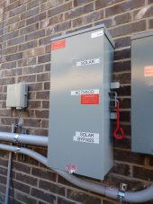 Bypass.JPG161.1 KB · Views: 312
 -
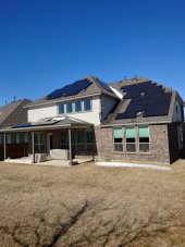 Snowy Panels.JPG198.5 KB · Views: 307
 -
 Full Day.gif55.7 KB · Views: 366
Last edited:
 I can't imagine seeing 38+kW load.