diy solar

diy solar

2x Sol-Ark 15K's + HomeGrid Stacks

Trevor,
Since I over think everything...
The manual states (pg 39) that CTs should be installed upstream of everything except for a Gen transfer switch, knife blade disconnect, etc. I've added (on paper) a separate PDB so that I could install the CTs downstream of the connection going to the knife blade disconnect. My drawing is attached. I'm not sure how your Solark will act if you throw the knife disconnect but maybe depends on settings. I was hoping to save money by only having 2 PDBs (or fewer Polaris lugs) after seeing your setup but to comply with the manual I might need 3. Not sure but I sure do appreciate this discussion.

Ray
I think you might be overthinking it. I just went off the standard 2x15k and 3x15K wiring diagrams on pg 13-14 which shows the CTs installed upstream of the 200A main disconnect.

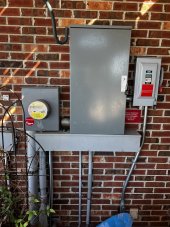
By the way...if you're being inspected make sure your inspector won't shoot down the Polaris type lugs. As soon as my city inspector got out of the truck he said something to the effect of "there better not be any Polaris lugs." :rolleyes:

Also, what are you doing with the Neutral from the grid? She's gone man!

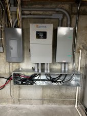
Something to consider is inverter maintenance. If I'm seeing everything correctly, the trough is supported by both inverters. What would he need to do if one inverter needed removed? Temporarily support is from below? Add some big shelf brackets underneath?
Yeah...that's a bit concerning. I mean between other inverter and the three conduit lines through the wall the trough is somewhat suspended but I'm not sure it'll be enough. I'll tackle that when I get to it. As slick as it looks right now I would have rather had a 12x12 hung off the wall with some decent air between the bottom of the inverters and the trough.

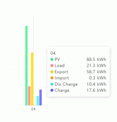
EDIT: You guys want a laugh? Check out the attached. I might have overshot February's requirement. ?‍?? Eh well...I'm gonna need every watt of that when it's 109-110F outside in mid-July.
 

Attachments

  • Feb 4th Wrapup.gif
    Feb 4th Wrapup.gif
    18.4 KB · Views: 38
  • Feb 4th Wrapup2.gif
    Feb 4th Wrapup2.gif
    56.2 KB · Views: 39
Last edited:
Great looking install. Thanks for sharing. I can't quite tell but did you use 2/0 wire downstream of your PDBs back to your transfer switch and then to your main panel? I have 2 Solark 15ks still in the box in my garage and I'm hung up on if that wire should be rated for 200amp or 400amp. The breakers on each Solark is 200amp so the combined should be 400amp but I also know that the breaker at my pole downstream of the meter is 200amp. Theoretically it should be impossible for the combined solark load wire to reach that amperage. I'm curious to how others are handling it. I commented on Engineer775 latest video asking the same question but no reply yet. Thanks!
L1/L2/N everywhere is 2/0 copper. I ultimately came up with the same answer as you (as evidenced by my install config) but I'm not without concern. Is it possible to draw say...160A continuous from the grid then supplement it with PV/battery to meet a load beyond 200A? I bet it is. I've lived here in this new house with no issues for 16 months on a 200A breaker so I'm not too concerned with my current load profile BUT I'm not going to be adding additional load to my main panel without some additional thought and measurement. Good thing I have a whole house load-meter built in now. :p I can't imagine seeing 38+kW load. o_O My record so far is 11kW.
L1/L2 for 200A is normally 3/0 copper. N can be 2/0.

You have 200A breakers? Then that should protect the wire. Those PDBs are rated for 620A.
 
I think you might be overthinking it. I just went off the standard 2x15k and 3x15K wiring diagrams on pg 13-14 which shows the CTs installed upstream of the 200A main disconnect.

By the way...if you're being inspected make sure your inspector won't shoot down the Polaris type lugs. As soon as my city inspector got out of the truck he said something to the effect of "there better not be any Polaris lugs." :rolleyes:

Also, what are you doing with the Neutral from the grid? She's gone man!


Yeah...that's a bit concerning. I mean between other inverter and the three conduit lines through the wall the trough is somewhat suspended but I'm not sure it'll be enough. I'll tackle that when I get to it. As slick as it looks right now I would have rather had a 12x12 hung off the wall with some decent air between the bottom of the inverters and the trough.

EDIT: You guys want a laugh? Check out the attached. I might have overshot February's requirement. ?‍?? Eh well...I'm gonna need every watt of that when it's 109-110F outside in mid-July.
Sorry, I didnt finish the neutral in the wiring diagram. Thanks for noticing. Again, I appreciate all your comments and advice.
 
I have not installed mine yet and have not thought about doing it that way, but it would sure save both space and materials.

Anyone know if there’s any codes that need to be complied with for clearance of wireway to inverter?
I would use 1/2" long nipples between the wireway and inverter to keep from damaging conductors. The wireway also needs independent support; a shelf bracket should do the job easily enough.
 
By the way...if you're being inspected make sure your inspector won't shoot down the Polaris type lugs. As soon as my city inspector got out of the truck he said something to the effect of "there better not be any Polaris lugs." :rolleyes:
Odd. Hands down the second best solution after compression splices. What gives some inspectors pause is insulation piercing taps, although I have had a good history working with them.
 
Hi. Your bypass/Manual transfer switch-what's that for? Also, is the switching instant? It do lights/computers turn off. Thanks
 
Hi. Your bypass/Manual transfer switch-what's that for? Also, is the switching instant? It do lights/computers turn off. Thanks
Those are break-before-make, so computers will drop and lights will blink. It's a good safety mechanism in case you have a failure or need to replace the inverter.
 
Those are break-before-make, so computers will drop and lights will blink. It's a good safety mechanism in case you have a failure or need to replace the inverter.
thanks!!! So they only blink correct? not go completely out? thats what Im looking for. what model is that please
 
thanks!!! So they only blink correct? not go completely out? thats what Im looking for. what model is that please
I use a manual transfer switch so it does drop power for the time it takes to throw the switch. I suppose you could use an ATS which would make the switch very fast but like everything it’s more money.
 
thanks!!! So they only blink correct? not go completely out? thats what Im looking for. what model is that please
My bypass switch is primarily there to bypass the inverters in case of failure and will absolutely cut power to the house momentarily while being actuated in any way. It's still not a 100% maintenance solution either as I'll also have to deenergize and safe the inverter's grid input circuit (amongst other things).
 
I use a manual transfer switch so it does drop power for the time it takes to throw the switch. I suppose you could use an ATS which would make the switch very fast but like everything it’s more money.
hi, which switch do you use?
 
My bypass switch is primarily there to bypass the inverters in case of failure and will absolutely cut power to the house momentarily while being actuated in any way. It's still not a 100% maintenance solution either as I'll also have to deenergize and safe the inverter's grid input circuit (amongst other things).
yeah, Im looking for something I can switch daily, not an emergency solution. I think they call it a quick make/quick break transfer switch.
 
Switch daily with a mechanical switch? Sounds like an application where you might want inverter to switch by means of its relay, or to simply change between charging battery and inverting from battery without switching.
 
Switch daily with a mechanical switch? Sounds like an application where you might want inverter to switch by means of its relay, or to simply change between charging battery and inverting from battery without switching.
Is that possible with an off grid inverter? A hybrid solution will not work for me because I need something that CANNOT export to the grid, ever.
 
An off-grid inverter like mobile would probably have an input relay that switches both line and neutral, and dynamically bonds neutral to ground.
When grid (shore power) is present, it connects to that and passes power through. When grid goes away it switches to off-grid. All you would need is a relay to disconnect Line and trigger that. But management of PV and battery SoC may not be a feature of it. Maybe the imported Chinese inverters would, quite a few features. Some use separate battery charger so PV too, others switch between grid and inverter.

There are inverters which support extra local consumption, blending inverter output with grid so draw from grid never exceeds a certain current. They may also support export to grid, or export to upstream house loads but not to grid (using CT). My Sunny Islands can be programmed to export to grid or not. To limit input to e.g. 15A from a 120V circuit, while supplying 120/240 or 120/208Y to loads. They can inverter from battery to supply additional load, or interact with AC coupled GT PV inverters to do the same. Again, either allowing GT PV to backfeed grid, or not. Same if fed from a generator, prevents backfeed. (perhaps a second of backfeed before responding?)

I would think SolArk could do this too, although might have momentary backfeed. Anybody know how SolArk uses generator input - if generator is operating, does SolArk add power from inverter? Thinking of feeding grid into generator input.

With Sunny Island, don't think it has great selection of PV/battery/grid management functions. It can operate off-grid until some DoD reached, then connect to grid and recharge while still using AC or DC coupled PV. It has some time-based switching.

To absolutely, positively, never backfeed grid even for an instant, might use a grid-powered battery charger.

I've toyed with the idea of rectifying grid into a Sunny Boy GT PV inverter, and setting its frequency-watts parameters to curtail first. Below 60.5 Hz, it would deliver full power. From 60.5 Hz to 61 Hz, the power it delivers from grid would ramp down. From 61 Hz to 62 Hz, the power PV inverters deliver would ramp down. This would use up to 100% of PV first, and use grid to keep batteries at float.
ok thanks. hybrid inverter is not an option for me. the ideal would be an off grid inverter that can blend AC and solar. short of that, I can wire a breaker that can turn off ac input to the inverter when I don't want to use grid power

the more i research this the more i get closer to a workable solution. thanks very much for your input.
 
An off-grid inverter like mobile would probably have an input relay that switches both line and neutral, and dynamically bonds neutral to ground.
When grid (shore power) is present, it connects to that and passes power through. When grid goes away it switches to off-grid. All you would need is a relay to disconnect Line and trigger that. But management of PV and battery SoC may not be a feature of it. Maybe the imported Chinese inverters would, quite a few features. Some use separate battery charger so PV too, others switch between grid and inverter.

There are inverters which support extra local consumption, blending inverter output with grid so draw from grid never exceeds a certain current. They may also support export to grid, or export to upstream house loads but not to grid (using CT). My Sunny Islands can be programmed to export to grid or not. To limit input to e.g. 15A from a 120V circuit, while supplying 120/240 or 120/208Y to loads. They can inverter from battery to supply additional load, or interact with AC coupled GT PV inverters to do the same. Again, either allowing GT PV to backfeed grid, or not. Same if fed from a generator, prevents backfeed. (perhaps a second of backfeed before responding?)

I would think SolArk could do this too, although might have momentary backfeed. Anybody know how SolArk uses generator input - if generator is operating, does SolArk add power from inverter? Thinking of feeding grid into generator input.

With Sunny Island, don't think it has great selection of PV/battery/grid management functions. It can operate off-grid until some DoD reached, then connect to grid and recharge while still using AC or DC coupled PV. It has some time-based switching.

To absolutely, positively, never backfeed grid even for an instant, might use a grid-powered battery charger.

I've toyed with the idea of rectifying grid into a Sunny Boy GT PV inverter, and setting its frequency-watts parameters to curtail first. Below 60.5 Hz, it would deliver full power. From 60.5 Hz to 61 Hz, the power it delivers from grid would ramp down. From 61 Hz to 62 Hz, the power PV inverters deliver would ramp down. This would use up to 100% of PV first, and use grid to keep batteries at float.
I use grid input with an ATS for my generator. I do not have to worry about back feeding the grid as the ATS completely isolates my gen from the grid.
 

Attachments

  • 48AAC34E-E1C6-4D48-AAD8-3A622611B573.jpeg
    48AAC34E-E1C6-4D48-AAD8-3A622611B573.jpeg
    1.2 MB · Views: 34
Back
Top