diy solar

diy solar

3 4s packs, each with their own Daly BMS in parralel. Why doesnt this work :(

bain19

New Member
Joined
Feb 2, 2021
Messages
12
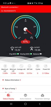
I think my daly bms's are causing me issues when i use them in parralel. when I run a high current load, like an rv furnace or rv fridge. I can see one battery pack take the entire draw/load. If I tell that bms to stop discharging the entire load will move to a different battery pack.

why is one battery taking 100% load vs all 3 batteries sharing some fraction of the load ?

my setup, what I've built:

3 4s1p 12v battery packs.
each pack has its own bms.
all the packs are wired into my RV power center(progressive dynamics), in a parralel configuration using a common bus(not daisy chained).

if the daly BMS's are the issue, is there a bms that works well with neighbors/parralel ?
 
Last edited:
I don’t know about the Daly’s…

Are all the cables to each battery exactly the same? Length, size, etc.

Do you have a clamp on multimeter that reads amps to verify that the other two batteries really are drawing zero amps?

Maybe post a photo?
 
also worth mentioning. the issue is only with discharging. The batteries charge properly in parralel, charge load shared across packs.
 
I don’t know about the Daly’s…

Are all the cables to each battery exactly the same? Length, size, etc.

Do you have a clamp on multimeter that reads amps to verify that the other two batteries really are drawing zero amps?

Maybe post a photo?
the lengths are not exactly the same,but their close. The packs are identical. I'm tracking draw through the daly app.

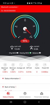
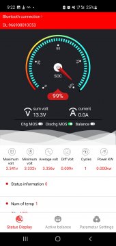
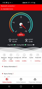
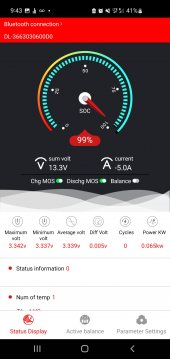
here are 3 cells.
Screenshot_20220930-212203_SMART BMS.jpgScreenshot_20220930-212219_SMART BMS.jpgScreenshot_20220930-212233_SMART BMS.jpg
 
I know you are discharging so here is probably a stupid question. What happens if you turn on chgMOS on the 2 BMS that are not allowing current flow?
 
I know you are discharging so here is probably a stupid question. What happens if you turn on chgMOS on the 2 BMS that are not allowing current flow?
it moved the draw/load.

I enabled the charge mosfets in the bms app, one by one, in this pack order.

79
53
D0

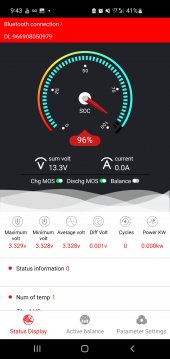
this is what I get now.
Screenshot_20220930-214306_SMART BMS.jpgScreenshot_20220930-214322_SMART BMS.jpgScreenshot_20220930-214336_SMART BMS.jpg
 
Seems like the total load went down to -7.4A (-5.0A + -2.4A) where before the one BMS registered -10.3A. So I'm wondering if the fist BMS showing 0 is actually correct or has -2.9A on it which would total the original -10.3A or did the total load really decrease? You probably need a DC clamp meter, sometimes called a Hall Effect meter, to pin this down.
In any case, its clear that one of the batteries is flowing better than the others. You need to check all the connections for cleanliness and proper torque if that's possible. There is uneven resistance in the cable system somewhere. Not sure what else to suggest.
the change in load is more related to whatever is running in the RV.

as an added detail. I can manually move that 7.4a load around to any one of the 3 bms's,
by disabling the battery and individually they measure/read the load as 7.4a. so that makes me think the wiring and connections are OK.
 
Here is my current guess.

The batteries are all hooked up to one post along with the load. (Is that correct)

What is the order of the wires on the posts (both positive and negative posts).

Is the load the bottom terminal
The battery that is always running is next, etc…
The way it’s connected is causing a difference in resistance in each battery.

You may need a nice 4 terminal bus bar.
 
I have two 302ah EVE 12v battery set ups. 1 has a Daly 200A BMS. The other has a JBD 200A BMS.

I have a similar problem. When I am running on the batteries, it seems like the load will be drawn out of one battery. If I switch off the discharge [using app] the load will go to the other battery. When I switch on the BMS, the load will equally be drawn out of both batteries. I wish I can remember which battery is not allowing a discharge and I want to say it's both [randomly switches] but I cannot say for sure. I do know that switching one of the BMS's on then off allows the load to be shared.

I am not certain what would happen if I left it alone and see if the load would equally be shared as the battery drained down.

As mentioned above by the OP, the charging side of this is not effected. If both batteries are equally discharged, they seem to be charged at the same/similar rate.

I am new to this DIY battery hobby so I just suspected it was because of the two different BMS's. I am in the middle of building a third 302ah CATL battery using a JBD 200a BMS but it is not even put together or installed yet. I was waiting to see how this third battery worked out before asking a question but since this thread is open, I figured I would throw in my experience into the ring.

I look forward to hear what you find and I suspect it's with the Daly BMS but I have no idea.
What's your wiring setup look like?
Lengths for each pack?
 
My packs look good :)

Sorry, I do not have any pictures but the gauge of wiring is 1/0 if I recall. The cables to the BMS is stock on the Daly and a similar gauge for the JBD. Sorry, I just do not have time to tear things apart and rarely take pictures during my build.

I understand wiring and electrical and I get the concept of voltage drops and what not, I just do not see how this has anything to do with problem. I we are talking about a 20A draw and it only 'turns on' one BMS that does not seem to be such a large draw that there would be a problem. The cable length differences, between the two, are probably not more than 4 inches and I'm willing to say around 2".

I just do not see that this is a cable issue. I honestly believe it's a BMS issue and once I get the third battery pack up and running, I will have more information to determine if I should dump a good working Daly for another JBD. Time will tell.
 
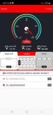
I wonder if the updated daly app will make a difference this season Screenshot_20230430_142735_SMART BMS.jpg
 
My packs look good :)

Sorry, I do not have any pictures but the gauge of wiring is 1/0 if I recall. The cables to the BMS is stock on the Daly and a similar gauge for the JBD. Sorry, I just do not have time to tear things apart and rarely take pictures during my build.

I understand wiring and electrical and I get the concept of voltage drops and what not, I just do not see how this has anything to do with problem. I we are talking about a 20A draw and it only 'turns on' one BMS that does not seem to be such a large draw that there would be a problem. The cable length differences, between the two, are probably not more than 4 inches and I'm willing to say around 2".

I just do not see that this is a cable issue. I honestly believe it's a BMS issue and once I get the third battery pack up and running, I will have more information to determine if I should dump a good working Daly for another JBD. Time will tell.
ever get that third battery going ?
 
If you have the charge/discharge turned off on one of the batteries, that one will no longer be balanced with its partners. I'd turn on all the MOSFETs, let them charge and discharge for a cycle or two, then compare the readings to see how well they are sharing.
 
Back
Top