Hi. I'll try to keep this short and to the point. I just ordered and received three battleborn 100ah 12v batteries and I have a lot of questions for anybody willing to help me out.
I'm trying to prioritize my next steps carefully. I am about to order a Victron Multiplus 12/3000/120-50 inverter charger from amazon. Also I think I will go ahead and pick up Victron BMV-712 Battery Monitor which brings me to a question. This monitor comes with or without a temperature sensor. I'm not really sure what the sensor is for or if I need it so if nobody can tell me I'll just go ahead and buy the sensor and figure it out later.
Ok great, now I will have the batteries, battery monitor, and the inverter charger. My next step is figuring out what all I need to get to be able to plug all this stuff together. I assume I will need a 30 amp shore inlet plus a 10/3 wire from it to the inverter. I do not have a 30 amp hookup at my house (yet) so I will just pick up a 30amp to 15amp adaptor.
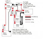
Ok, now I have power from my house to this inverter. So far I feel comfortable with everything but now I need to bridge the connection from my battleborn batteries to the inverter. I have been looking at various diagrams online and so far I found one I think might be best for me. The link is
https://www.explorist.life/600-amp-hour-875-watt-camper-van-solar-kit/
They recommend 2/0 AWG wire from the batteries to the bus bars, so my next question is would it be better to use 4/0 AWG? Is there a downside in oversizing your wire?
I have not came across a youtube video or article yet that explains how to wire the batteries up step by step. I assume I will first need to ground the negitive bus bar to my vans frame first and get the bus bars all set up and wired to the inverter before I actually connect my batteries to the bus bars. Next brings me to a very important question.
:::
Do I hook up all the positive wires before all the negative wires? I feel like I'm about to get bashed by this question and told to just have an electrician do it for me but I want to learn this stuff and do it on my own so I guess I'll just do some heavy research before wiring them up
:::
So that is pretty much where I am on this electrical build. I bought a diesel heater that I can't wait to set up, its getting pretty chilly here in Oklahoma and I'm about to get a two week vacation from work and I really want to order the parts I need before the end of this week and really dig into this stuff and accomplish something.
Thanks again.
Vancave.


