diy solar

diy solar

30 Amp mains-POWERsupply + MPPT Solar 60 Amp + DALY BMS 400A + ARDUINO

rudydevolder

New Member
Joined
Jul 15, 2020
Messages
18
I want some advice because I am not sure which configuration is best and how to improve:
Notice the micro-controller (I program myself) that is connected to:
  1. The AC/DC mains connected power-supply: MeanWell CSP-3000/120 (Mains-AC to DC 30 AMPS): Can be remote controlled in either CV or CC modus. Also remotely controlled to power ON/OFF. And the max. output voltage is 120V DC can be lowered through either a potentio-meter or an external controlled voltage controlled by an ARDUINO. I plan on using an ARDUINO controller programmed myself. I plan to use this power-supply as some kind of backup or added power for my heavy load which is actually a 10Kw / 60 Volts BLDC-motor for my cable cart. But the cable cart is only working few times a day. The 30 Amp load is my house and so can be connected directly to the load output of my MPPT which is limited to 30 Amps.
  2. DALY BMS: the one I already have is a 400 Amps common port and can be remotely controlled through RS-485.
  3. MPPT solar controller model TYC-60A60V: so 60 Amps 60 volts; has also RS-485
  4. 200 Amp load: 10 Kw BLDC motors controlled by a Kelly BLDC controller which has CAN-bus and analog inputs/outputs.
VERSION 1:
=====================================================================
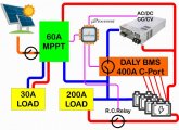
My-Solar-config.jpg
In this configuration I could use actually a cheaper and smaller BMS since the 200 Amp load is directly coupled to the batteries. The Remote Controlled relay is a protection I put to protect the batteries from overloading it with some voltage and current sensors. Actually it is already protected in the Kelly motor controller to protect batteries.


Version 2:
=======================================================================
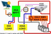

My-Solar-config v2.jpg
Here I use the setup Will uses with the mains-charger and Daly BMS in series.

My hobby is electronics and programming: I use the ARDUINO to get diagnostics via the RS-485 bus on both my DALY BMS and MPPT controller. So, I also can reprogram the parameters in both controllers on the fly. I was thinking to charge primarily via SOLAR until a state of charge of 80 percent is reached and top it off using the mains to go through the DALY BMS with higher voltage settings and balancing the whole pack.

My questions:
Q1: Like I said configuration 1 will also work since I have my expensive 400 Amp controller already I think I'll go better for config 2 to make it safer. But like I said my Kelly motor controllers have already battery protection build in. So, I think the BMS will dissipate unnecessary power. Any suggestions?
Q2: I can charge through both MPPT and MAINS at the same time, no? Especially when my batteries getting low or the heavy motor-load comes in. Maybe I need to regulate the voltage of the mains-supply to a slightly lower voltage to give the Solar power priority?
Q3: Putting a DIODE in series to avoid power running into my mains-supply when it is remotely switched off; needed?
Q4: Concerning the operating modus of my DC power supply: CC or CV:
I'm afraid to work in CC modus since my power-supply can deliver 120 Volts it can destroy my BMS. I didn't test yet but I think in CC modus I can't put a max. voltage it's either CC or CV when I look into the data-sheet:​
  1. I think I can just charge using the CV-modus and limit the current through my DALY BMS to avoid my power supply to go in overload-protection?
  2. Or do I need to put it in CC-modus and limit the current to 30 Amps? Than I'm afraid the Voltage can go to high when the battery is almost full; the DALY BMS will protect?
  3. I can also program everything to go from CC to CV automatically when the Voltage is above a certain level but that make it more complex.
Q5: Do I need to change/protect more?

Any help is appreciated.
 
Last edited:
On both versions listed, neither protect the battery from the MPPT. Consider placing the Daly closest to battery negative.
 
You mean I must place the mppt in series with the Daly parallel with the meanwell powersupply? But I think my mppt has already a charge controller inside? But not a BMS. In my mppt I can program the type of batterie, floating voltage, equalizing everything. So it should stop charging when full, no? And the Daly has actually a cc circuit to limit the current from the cv powersupply, no ?
 
The Daly should measure ALL current in & out of the battery, and should therefore be the only thing connected to B-. All other equipment should be connected to P-.
 
OK, I understand it is better for the statistics and tracking of the health of the batteries. I think I will follow this advice. I will do some tests before I hook everything up. And I will report my progress. Thanks for the advice.
 
But wait, than I have a problem when the MPPT is disconnected from the batteries. How to take care of that? That is why I've put the MPPT controller directly on the batteries. I don't plan to buy a new Daly with separate port on 400 amps. What I'm going to do with this one?
 
Have your arduino cut the PV in if the arduino reads that there is a over voltage situation. It looks like your Arduino can get the necessary info from BMS You coukld possibly use the RC relay you already have planned or a SSR controlled by the Arduino.

It seems to me like an arduino would be a great controller for a solar system from your experience are they stable enough that you can set it up and walk away for years without worrying it will crash or something.
 
Thanks Craig!!! That's actually the answer I was hoping for. So, the overvoltage message will come from the Daly? I was thinking from the MPPT? And I wonder how many milliseconds are needed to react? Anybody an idea how fast that overvoltage builds up?
 
Last edited:
But I am not 100% sure about the stability of the Arduino. That depends more on the libraries I will be using I think and of course I can make a mistake myself. I'm thinking about using even a secondary Arduino or something else that functions as a watchdog for every few seconds. If the watchdog doesn't get his feeding in time I could also switch of the PV. Using the same relay.
 
The micro has a built in hardware watchdog that will reset the processor if you don't poke it what ever interval to cover coding problems causing a lockup etc.
 
Thanks Craig!!! That's actually the answer I was hoping for. So, the overvoltage message will come from the Daly? I was thinking from the MPPT? And I wonder how many milliseconds are needed to react? Anybody an idea how fast that overvoltage builds up?
It does not need to react all that fast actually I would plan on having a but if a delay so a sudden spike or bad reading dies not throw things off. I would average the voltage over a few readings. Then have processor make a decision. I had to do this with my cell tester every once in a while I got a bad reading and it prematurely thinks battery is empty.
 
I read about MPPT controllers blowing up because of disconnection of the batteries. But what I didn't know was that the output voltage of the MPPT rises before it blows up. That would go faster when the power of the Solar panels is on the limit that the MPTT can handle I think.
 
The main job of a BMS is to protect the batteries. Typically the battery bank is one of the most expensive parts of a system. It will monitor all of the cells and open the connection if any single cells goes to too high or too low of a voltage.

Your loads should disconnect at a safe low battery limit, and the charge controller should be set to stop charging at a safe limit. So if everything is working correctly, the BMS will never need to disconnect the load or charge current. It is just there for when something bad does happen. If a cell is going over or under safe voltage limits, it is much better to shut down and correct the problem before a battery is damaged or catches fire.

If your Arduino can check the status every 5 seconds it is plenty fast to be safe. Have it give you a warning if things are getting close so you can choose to stop the cable car or turn off the charge controller safely. Averaging at least 4 readings is a good idea to smooth out spikes. A few seconds of low voltage from starting a motor is not a problem for the battery, as that is the internal resistance, not a true cell voltage state. But if one cll keeps going low while the others don't, maybe you have one going bad.
 
But I am not 100% sure about the stability of the Arduino. That depends more on the libraries I will be using I think and of course I can make a mistake myself. I'm thinking about using even a secondary Arduino or something else that functions as a watchdog for every few seconds. If the watchdog doesn't get his feeding in time I could also switch of the PV. Using the same relay.
I've had arduino nano's die. I advise you to source a real Arduino
for your prototyping feel free to use the cheap Chinese clones but when your system is live use a pic with quality components on the board. A few extra bucks now can weed out the possibility of a more expensive problem later.
 
The main job of a BMS is to protect the batteries. Typically the battery bank is one of the most expensive parts of a system. It will monitor all of the cells and open the connection if any single cells goes to too high or too low of a voltage.

Your loads should disconnect at a safe low battery limit, and the charge controller should be set to stop charging at a safe limit. So if everything is working correctly, the BMS will never need to disconnect the load or charge current. It is just there for when something bad does happen. If a cell is going over or under safe voltage limits, it is much better to shut down and correct the problem before a battery is damaged or catches fire.

If your Arduino can check the status every 5 seconds it is plenty fast to be safe. Have it give you a warning if things are getting close so you can choose to stop the cable car or turn off the charge controller safely. Averaging at least 4 readings is a good idea to smooth out spikes. A few seconds of low voltage from starting a motor is not a problem for the battery, as that is the internal resistance, not a true cell voltage state. But if one cll keeps going low while the others don't, maybe you have one going bad.
Seems like a good idea but what about the balancing, if the charger stops charging below the threshold of the passive balancing than no balancing at all happens, right?
 
If all you have is a top only passive load balance, you could run into a balance issue, if your charger stops below the balance threshold. But you will still have protection if the cells do go enough out of balance that a low cell gets too low, or a high cell gets too high. And in the case of one cell going too high, it will still activate the balance load to try and pull it down.

Assuming a 14S LiIon pack, the full charge voltage would be 14 x 4.2 = 58.8 volts, but to extend the life, you set it down to just 57.4, or 4.1 volts per cell. The basic LiIon DALY BMS enables the balance load at 4.18 volts. So if the cells are well balanced, it's true, you won't have any balance current. This is not a problem, as the cells are balanced. If the pack goes a little out of balance, there really is not a problem, as long as the cells stay in the safe range. If a cell does start going too high, it only has to be high by 0.08 volts to get balance current in this case. If the rest of the cells are balanced, they would all be at 4.094 volts. Most likely there will be a few mv difference across the cells, but that is not too bad. If you want to keep them closer, use an active balancer. You can run an additional balancer along with a BMS. If the cells get out of balance on the low side, a passive load balancer can't do anything anyways. If the balance does get very bad, the BMS will still disconnect the load if any cell goes below the low voltage shut off. On the DALY this is 2.8 volts. That is pretty low, but it is also when the cells are under load. This is enough to keep you from destroying a cell. If the load (inverter?) is set to shut down at more than 3.3 volts per cell (42 volts), it is unlikely the BMS will ever trigger on a low cell volt error, but it is there as an extra safety in case a cell is getting weak and does fall that low. If everything is working right, the BMS does nothing, it is there for when something goes wrong.

After a lot of research, I did end up getting a BMS that has active balancing built in. This will pull energy from the highest voltage cell and push it to the lowest voltage cell at any state of charge. With a well balanced pack, this may be a bit overkill, but I saw no downside to having this capability. I am planning on having my charge stop at 4.1 volts per cell and the inverter shut down at 3.3 volts per cell. That works out to charging to about 85% and discharging no less than 25%. With the cost of the batteries, it makes sense to protect them and extent their lives.
 
Back
Top