diy solar

diy solar

4 405w panels vs 12 100w panels...

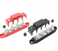
What's your thoughts on using a 250 amp audio busbar vs a 250 amp blue sea bus bar?

Not finding examples of audio busbars.
Audio stuff is often rated for peaks. Power systems need to handle continuous current.

Busbar usually means connecting multiple batteries or multiple inverters, in which case I can arrange them so busbar only handles half the current at any point of its cross section.
If only one battery and one inverter, I'd stack on a single bolt (possibly top/bottom of busbar) so none of the current goes through busbar cross section.
 
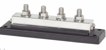
I could not find the happy medium between the audio busbars which I did not like and the Blue Sea busbars which are awesome, but pricey. I looked at do it yourself, or having someone fab one, but I gave up and decided to get my system built.

When I was first recommended a busbar for my solar build, it was a 250 amp audio distribution bar. Many people use these for solar builds. I rechecked my current, and taking into account a 2000 watt inverter, a low voltage cutoff of 10.5. plus a fudge factor, I could exceed that 250 amp rating.

This is the forty dollar 4 post with 5/16 inch stud 250 amp busbar I ordered and decided not to use:
1614203593495.png
For $220 for two of these plus $42 for covers, This is what is more than adequate for a solar build, a blue sea four post 5/16" stud 600 amp busbar:
1614204207321.png
For another 12 volt 50 amp 2 AWG wire to 6 AWG connection, I used rings and bolts with the positive and negative cables in their own separate project box. I did not splice, because this needed to be removable.
 

Attachments

  • 1614204178681.png
    1614204178681.png
    16.5 KB · Views: 0
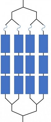
Either 3 pairs "Y" or one pair of 4:1 would work.
You may need a few short cables to make things reach, can attempt to sketch out.

Rather than 3 "Y" at the same level as you've sketched (with probably ore connections than can be made,

Two "Y" plug into one "Y" to make 4:1

Two panels join with "Y" as a parallel pair. Two more panels join with "Y" as a parallel pair. Those two pairs join with third "Y" as 4:1

You should also get MC fuse holders, and fuses of the value shown on panel label.

If you use "Y" cables, then no need for combiner box, just run MC cables back to charge controller.

Alternate to "Y" cables is a box with metal bar to connect several cables (like neutral or ground bar in breaker panel). Typically also has fuse holders or breakers for positive.
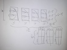
i cant seem to wrap my head around this wiring. Do these sketches make sense? Can someone draw a sketch of 3s4p panel wiring?
20210225_180648.jpg
i like the idea of the Y connectors conncted with Y connectors. Thats what ill do. Can someone sketch where the fuses will go? Or i suppose tell me but im really more a visual person. Im thinking a fuse will go just above the Y connector.

how many fuses will i need total?
15amp? How many?
50amp is one.
150 amp is one?

if someone could sketch the layout it would really be helpful.
thank you
 
3s4p with fuses.
Each fuse is whatever value shown on PV panel label, probably 10A, 15A, or 20A

3s4p fused.jpg
 
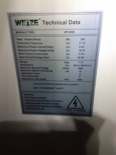
Fuse is 12A as printed on the sticker.
so if the max is 12A that means i should get 10A? Or should i get 15A holder and insert 12A fuse in it? I dont see any 12A fuse holders and fuses. Only 10 or 15A holders but I can find 12A fuses. What do these fuses do? Are they absolutely neccesary for a solar setup?
 
If you fuse each row as shown in Hedges' drawing, then 10 amps on each string would be fine. They are rated to 12 max, but the ISC current is only 5.7 amps, so the 10's will work without a problem.
 
You will use MC4 Fuse holder and fuse.
Example: https://www.ebay.com/itm/RICH-SOLAR...use-Holder-Fuse-10A-15A-20A-30A/143598764627?
You can use 10A which is almost twice rating of the panel shorted circuit current of 5.70A, or shop around for 12A fuse.
You will use MC4 Fuse holder and fuse.
Example: https://www.ebay.com/itm/RICH-SOLAR...use-Holder-Fuse-10A-15A-20A-30A/143598764627?
You can use 10A which is almost twice rating of the panel shorted circuit current of 5.70A, or shop around for 12A fuse.
i can get 4 of the fuse holders you just mentioned and 6 of these y branch connectors:

that should set me up jyst fine from the panels. Then i will need a 50a fuse just before the scc such as:
will that one work? Is that correct so far?

i will need 8awg wires at that point so does that require a particular 8awg fuse or would it not matter?
 
3s4p with fuses.
Each fuse is whatever value shown on PV panel label, probably 10A, 15A, or 20A

View attachment 38628
I may have to lie them all in a single row
20210226_012003.jpg
can you verify if my numbers are accurate regarding the amps and voltage per string? Did i do this reversed? This is 3s4p. Im tring to figure out fusing. I will simply need 1 fuse per y only on the hot side. 4 fuses. But wouldnt i need hgher than 10a fuse because of the series? When im looking at fuses it mentions rated for 250v and others. Is that number important too? Should i be looking for 1000v 10a fuses?

im so confused. It seems like the last step is the hardest part. Lots of fuses say 10awg. None say 8awg. Thats ok i think because 8awg will come after second set of y connectors.

can someone show m a good busbar for my setup that is also inexpensive. I did not include that or fuses within my initial budget and this has thrown me off a little bit.

also, the battery manufacturer is asking for 6awg wires for battery connection and loading. Why would they be saying this and I am told here 2/0awg should be used? Should i be alarmed at the discrepency? What could be the reason for this and would this possibly make or break my system? Thanks!
 
Each string will produce 5.70A shorted circuit current, so you have 4 strings in parallel, the total current will be 5.70 x 4 = 22.80A, so 30A or 40A fuse will be OK.
Each panel has Voc of 22.64V, so 3 panel in series = 22.64VDC x 3 = 67.92VDC, for safety margin when cold the Voc will be about 70 ~ 80VDC so 250VDC fuse rating is fine.
Your drawing looks very confusing,
You can also use 1 to 4 MC4 branch connectors, and it looks like you may need some MC4 Solar extension wires if all the wilres canot reach the branch connector.
Or 1 to 4 MC4 wire branch connector.
 
The voltages do add, but you should do the math on the VOC maximum voltage. Your panels' VOC rating is 22.64 volts each, so the string of 3 in series adds up to 67.92 volts. And it could climb over 80 or so if it gets very cold in your location. It is always good to allow at least 20% margin in case of a cold snap, like Texas is having. Even if it does not normally get cold, it could happen, and it just takes one cold morning to fry a charge controller.

Each series string will have the same current as a single panel. So the current would be the ISC of one panel or 5.7 amps. That is where your 10 amp fuse will go. After you combine 2 of the groups with "Y" connectors, the current will double to 11.4 amps. And after the last "Y" connectors, the current doubles again to 22.8 amps.

In ideal sun conditions, the maximum power point voltage should be 3 x 18.78 = 56.34 volts, and the current should be 4 x 5.32 = 21.28 amps. Multiply those and we get 56.34 x 21.28 = 1198.9152 watts. Yeah, we can call that 1200 watts. Of course, that is just at Solar Noon, with the panels angled right at the sun. That works out to about 1/4 of my system. I have 16 x 300 watt panels. Here in So Cal, I just made 25 KWH's yesterday. If you were in the same area, you should get 6.25 KWH in a similar day.

Depending on where you live, you may need to add "Rapid Shut Down" up at the panels.
thanks. That is very helpful to me how you explained it. How would i know if i need the rapid shutdown? I live in the mountains at 3500ft elevation. In wintertime averages 59 daytime, 35 nightime and Im estimating. I think 20 degrees would be lowest ever and a rare extreme. Im in california, not washington or idaho.
 
Each string will produce 5.70A shorted circuit current, so you have 4 strings in parallel, the total current will be 5.70 x 4 = 22.80A, so 30A or 40A fuse will be OK.
Each panel has Voc of 22.64V, so 3 panel in series = 22.64VDC x 3 = 67.92VDC, for safety margin when cold the Voc will be about 70 ~ 80VDC so 250VDC fuse rating is fine.
Your drawing looks very confusing,
You can also use 1 to 4 MC4 branch connectors, and it looks like you may need some MC4 Solar extension wires if all the wilres canot reach the branch connector.
Or 1 to 4 MC4 wire branch connector.
thanks for this info. Im understanding i need a 10a fuse per string (so 3 of those). I need a 40a fuse just before the cc. I need a 250a fuse before inverter. Please correct me if im wrong.

with the y cables i would like to connect 8awg wire just after the connector. They list 10awg to 14awg sizing from what i see. I know thats fine for the hook up. Will I be able to attach 8 awg afterwards. Sorry if this is a bonehead question. As I typed it I just thought, of course I can!

im going to get 6 y connectors rated at 40a. Is that overkill? I dont think so. I will get a small bundle of 12 awg red and black along with 8 mc4 connectors so i cn make my own lengths for any that dont reach. I will also need one of those special tools i think. I already have a crimper. Should i use heat shrink wrap at the connections?

regarding a bus bar, right now we use an extension cord plugged into the inverter ac outlet that runs to the house and it hooks power up to our outlets. Does that sound reasonable with this amount of power? Only running 200w and 1000w inverter right now with pwm cc.
 
If your system is never inspected, no one will know if you have rapid shut down or not, but if something goes wrong, you may not only injure a fireman on your roof, you could lose your insurance coverage. This is the sticky part. If you ask your local officials about the law, they will know you are doing something, and will expect you to pull permits etc. I could not risk it here, I had to pay a professional to install my solar panels up on the roof because the building codes here are crazy. The guy I used has done over 100 sites in this area, and he still had to go back and refile one of the document again. The permitting and all did add nearly $2,000 to the cost of my system, but the fine if someone complained about my panels and they found no permit for it, would have been way more. And if something shorted out and started a fire, my insurance would be voided. I would always recommend you get the building permit and follow the local codes. If it is a "portable" system, and the panels are separate from your building, then you can usually just DIY it and probably not have an issue. In my area, the rapid shut down it only required if the panels are on, or within 10 feet of a living quarters. Not sure it that would count on an attached or detached garage, but I do know a few have done solar panels on a car port without it. The problem is that you can't turn off the sun. Yank out all the wires, and the panels are still making power. If a fireman has to go on your array, they could be exposed to live wires. The idea of rapid shut down is that the lines will be powered down at or very near the panels, and clearly marked where they might still be live. I am in the north end of Los Angeles County, 30 miles north of Hollywood, and it is required here.

With 12 panels, in 3S 4P you need 4 of the 10 amp fuses. You maximum current should never exceed the ISC 5.7 amps x 4 or 22.8 amps, so #10 awg wire is safe from a capacity standpoint, but depending on the length of the run, you may want to step up to a #8 to reduce loss in the cables. Most MC4 connectors though, can't really take a wire that large. It is always good to use parts that can handle more power than you need. The 40 amp rated connectors should last a good long time when running under 2 amps. With most cheaper electronic components, we tend to run them around 50% of rating. 100 amps on a 200 amp BMS, things like that. With wire and connectors, you can run them closer, but it never hurts to have less resistance and heat buildup with higher rated parts.

A 1000 watt inverter is still able to make a decent amount of power. Running that in an extension cord is not a permanent solution. Again, if this a "portable system" you might get away with it, but this is a safety concern. Your description sounds like that cord is outdoors. I get nervous having an extension cord running out for Christmas lights for a month. I always have it plugged into a ground fault protector, and it has tripped a few times, just from morning dew on the cables. Extension cords are considered a temporary use item. You can certainly use that for testing and running things for a bit, but if it is going to be used for weeks, you should run some permanent wiring. How long is the run outside? I have not had to run any outdoor feeds here, but I seem to remember the code called for a feeder line to be buried 18 inches deep. One of my friends ran a feed out to a hot tub in his back yard. You can get some 3 x #10 UF cable at most hardware stores like a Home Depot etc. Here is an Amazon listing for 50 feet. This is overkill for your current system, but if you ever expand, you won't need to dig a new trench.
This will handle up to 30 amps of 120/240 split phase power.
 
Back
Top