diy solar

diy solar

4 AWG wire vs 4/0 AWG wire

You say converter, did you mean inverter?
You mention 6 awg wire, did you get some of that as well?
The 6 awg is what’s already wired to the battery. What I mean by the converter is the electrical box with the fuse (WFCO wf-8995pec).
I’m installing a separate 600w inverter so that I can run one outlet for the TV, i do not want to do the big thing with a transfer switch.

so my question is can I have two separate circuit (one for what’s actually there) and one exactly like the one in Will’s tutorial plugged on the same three batteries in parallel?
 
What your are describing does not match the link.
If you draw something I will look at it.
 
I'm sorry, please use this updated file. I forgot the battery monitor and the shunt. Thanks again!
 

Attachments

  • Solar_Dominic.pdf
    41 KB · Views: 12
I'm sorry, please use this updated file. I forgot the battery monitor and the shunt. Thanks again!

Looks good.
Some guesses...
I guess this is Will's blueprint integrated into your RV setup, confirm?
I guess the 100 amp fuse between the power center and the battery is already in place and closer to the power center than the battery, confirm?

Some suggestions...
Use a 100 amp fuse directly off the battery + to a disconnect switch then fan out to the power center and fuse box.
The idea is so you can isolate the batteries with one switch.
If its convenient you could also replace the fuse and the switch with a quality breaker.
Should be as close to the battery as possible to minimise the chance of a short upstream.

Put a quality breaker on the solar panel input +.
This allows you to isolate the panels from the solar charge controller.

The 10 awg - wire between the solar charge controller and the fuse box can be terminated on a - screw terminal.
Just tweaks my ocd a bit the way it is.

What form factor are the 100 amp fuses?
Don't be tempted by cheap breakers, I suggest bussman.

Hope that is clear.
It is in fact pretty clear. I bought that breaker last week for my solar line, would you consider it a cheap one?
 
It is in fact pretty clear. I bought that breaker last week for my solar line, would you consider it a cheap one?

Yes cheap and scary.
Personally I would only use bussman breakers and bluesea or littlefuse fuses.

If you are lucky cheap breakers they too early, If you are unlucky they weld closed.
 
Yes cheap and scary.
Personally I would only use bussman breakers and bluesea or littlefuse fuses.

If you are lucky cheap breakers they too early, If you are unlucky they weld closed.
Haha ok so I might use it for the panel so that I don’t waste it. So I guess one bussman 100amp circuit breaker on each line, one for the fuse box and one for the power center?
 
Haha ok so I might use it for the panel so that I don’t waste it. So I guess one bussman 100amp circuit breaker on each line, one for the fuse box and one for the power center?

I would throw that breaker away or give it to someone I really detested.
I already asked but I will ask again, Is there already a 100 amp fuse between the power centre and the battery?
 
Code:
Generic base system

battery + -> mrbf_fuse -> main_wire -> disconnect_switch -> bus_bar -> (loads and sources)
battery - <- shunt <- main_wire <- bus_bar <- (loads and sources)
 
I would throw that breaker away or give it to someone I really detested.
I already asked but I will ask again, Is there already a 100 amp fuse between the power centre and the battery?
fuse.jpg
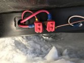
There is what seems to be a fuse bolted to the RV frame closer to the battery than the power centre. I attached a picture. I would get rid of that because everything is going inside within a diameter of 4 feet from the power centre. Hope I'm clear enough..
 
And also my wire that goes to the power centre can't be behind the switch because my fridge only works with electricity. So if I want to disconnect the solar system when we don't use it, I would also disconnect my fridge?
 
And also my wire that goes to the power centre can't be behind the switch because my fridge only works with electricity. So if I want to disconnect the solar system when we don't use it, I would also disconnect my fridge?

I've lost the plot, please update your drawing.
 
Last edited:
I'm sorry, I'm asking a lot of questions but believe me it will be done safe and right. My trailer is a 2020 Shasta 18FQ. Basically, the wiring that's already there goes from the battery to the power centre. It powers my 12v/110v only fridge and all other 12V lights and USB outlets.

I want to add an inverter and run a saperate outlet from the inverter to use my TV and charge my laptop. Based on Will's minimalist solar install, on which terminal on my diagram should the power cable that goes to from the power center end up? Does it go to the terminals on the fuse box (yellow and green lines) or direct to the battery terminals with a breaker in between.
 

Attachments

  • Solar_Dominic-2.pdf
    37.1 KB · Views: 6
What are the green and yellow wire going from the power centre to the fuse box?
 
What purpose do you think the green and yellow wire would serve?
 
For power, if I put the green and yellow wire, I would not have the red and black going to the battery, which I don't think it makes sense?

So basically, is it ok to have two seperate positive and negative lines, one for the inverter and solar controller and one for the the power centre (both with their own circuit breaker) ? That way I could add a switch to turn off the solar system when I'm plugged in shore power.

You are really good help, I can't thank you enough!
 
Back
Top