diy solar

diy solar

4 batteries: two of them drain to charge the others???

TommyHolly

New Member
Joined
Jun 24, 2021
Messages
207
Hello,
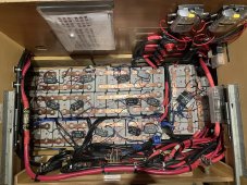
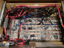
I re-installed 4 prismatic 300Ah LiFePo4 batteries in my boat a few months ago. Out of the 48 cells, I’ve constructed a 3P 4S system making 4, 300ah batteries at 1,200Ah. (See previous posts)

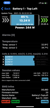
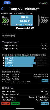
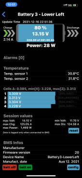
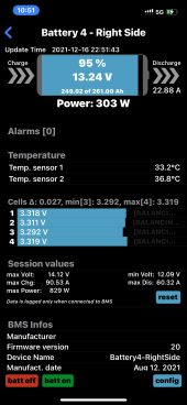
Each battery has its own Overkill Solar BMS. I’ve noticed that Battery 1 & 4 are constantly getting drained with 25A while Batteries 2 & 3 are actually CHARGING! wity 5A or so?? How can this happen?

All batteries are connected directly to the bus bar so they should all drain equally or all charge equally. Is there a way to connect the Overkill Solar BMS together so that they act as one whole system? It’s strange that two of them are charging while the others are draining…

This leads to a situation where Batteries 1 & 4 will shut off at 0% due to the BMS low voltage limit while Batteries 2 & 3 are still at 70%??? I find myself needing to shut off two batteries so that they drain or charge to balance them manually.

Please see pictures.
 

Attachments

  • D65D26C5-6486-4870-B07C-C4B08ABCB6ED.png
    D65D26C5-6486-4870-B07C-C4B08ABCB6ED.png
    563.6 KB · Views: 43
  • C6936A86-6D5B-47AE-9AC5-033769EAF6FA.png
    C6936A86-6D5B-47AE-9AC5-033769EAF6FA.png
    557 KB · Views: 25
  • 84C65105-429E-464C-849A-6F20FC3A23D1.png
    84C65105-429E-464C-849A-6F20FC3A23D1.png
    551.4 KB · Views: 24
  • 5AFD4B25-5857-4A79-B999-056447F16D9F.png
    5AFD4B25-5857-4A79-B999-056447F16D9F.png
    554.9 KB · Views: 43
  • 3714B075-0079-477A-848F-EC418375F36C.jpeg
    3714B075-0079-477A-848F-EC418375F36C.jpeg
    396.2 KB · Views: 52
  • 090AD3B9-063C-44BC-9D41-7230F92A3158.jpeg
    090AD3B9-063C-44BC-9D41-7230F92A3158.jpeg
    407.3 KB · Views: 51
Are all those little black boxes in the last 2 pics, active balancers?

If they are, first, take those off to rule them out, stop any charging or load circuits, top balance all the cells up to same voltage.

Check all of the paralleling cables, terminals and connections to the main bus bars, using voltage drop test to make sure all the parallel voltages are exactly same on all 4 banks, repair any issues there.

Turn back on your charging and load circuits (still no active balancers if any, are in the mix)... See if any other clues are revealed.

Basically want to try and simply things by removing any active balancers and get down to basic simple system for the testing, then re-introduce one thing at a time to make the obvious weed stand out in a forest...

In my opinion, if entire banks of 12v are going that far off from each other, I'd really be looking at all those parallel connections in there.

The last question is, is this a new problem? Or did it ever work properly, and then broke later?
 
Last edited:
I agree with @Samsonite801 , take off the active balancers. Eliminate the items that could be causing problems.

Is every positive cable the same length? Similarly, is every negative cable the same length? I don't think cables of varying lengths are going to account for the huge discrepancy you're seeing. But the question needs to be asked.

I think you need to shut down the system and independently charge each 3p4s battery to whatever is a full state of charge. Once they have all settled at the same voltage, reconnect them and see if there is charge/discharge action between batteries.
 
Are all those little black boxes in the last 2 pics, active balancers?
Yes, all those little black boxes are QNBBM Lithium Battery balancers which only help balance individual cells and not between the parallel batteries.

If they are, first, take those off to rule them out, stop any charging or load circuits, top balance all the cells up to same voltage.
I just re-designed the system a month ago. I top balanced everything and then capacity tested each and every cell to match them before I created the batteries.

Check all of the paralleling cables, terminals and connections to the main bus bars, using voltage drop test to make sure all the parallel voltages are exactly same on all 4 banks, repair any issues there.
When I made the parallel cables to the main bus bar, I made sure each cable was the same exact length and size. How do I perform a voltage drop test? Just by taking the readings at one end of the cable to the other?
Turn back on your charging and load circuits (still no active balancers if any, are in the mix)... See if any other clues are revealed.
No other balancers are in the mix besides the overkill Solar’s ability to do so.
Basically want to try and simply things by removing any active balancers and get down to basic simple system for the testing, then re-introduce one thing at a time to make the obvious weed stand out in a forest...

In my opinion, if entire banks of 12v are going that far off from each other, I'd really be looking at all those parallel connections in there.
Yeah, I’ll take a better look at the parallel connections.
The last question is, is this a new problem? Or did it ever work properly, and then broke later?
The boat when I bought it didn’t have a working system, most cells were damaged, no BMS or monitoring system was being used besides those balancers. With the help of people here over 6 months I redesigned the system. And it was working fine until the last week or so. The Victron Smart Shunt started saying the wrong capacity again and had to be manually reset, and then the batteries started charging differently. Also I noticed that somehow, the lead acid starting batteries are on the same circuit and I’m not sure how or why, it must be spliced to a cable buried deep inside the boat. Ugh.
 
I agree with @Samsonite801 , take off the active balancers. Eliminate the items that could be causing problems.
But the balancers don’t connect between batteries, only between the individual 3P cells of the 4S batteries? How could they effect the overall batteries?
Is every positive cable the same length? Similarly, is every negative cable the same length? I don't think cables of varying lengths are going to account for the huge discrepancy you're seeing. But the question needs to be asked.
Yes, when I re-designed the system I made all the cables the same length.
I think you need to shut down the system and independently charge each 3p4s battery to whatever is a full state of charge. Once they have all settled at the same voltage, reconnect them and see if there is charge/discharge action between batteries.
They do charge up to full voltage where all of them are 100%. The BMS will shut off the fully charged ones and allow more amps to go to the weaker ones until they are fully charged too.

But what I’ve been doing is once the stronger batteries 2 & 3 start getting charged by the weaker ones, I’ll manually turn them off with the power switches I installed or use the BMS app to shut them off so that the weaker ones can fully charge first.
 
I’ve constructed a 3P 4S system

Each battery has its own Overkill Solar BMS
That is not what the picture shows. It shows you have 3 cells directly strapped in parallel.

Thoughs particular pump switching balancers are just about worthless. At 0.1v cell voltage difference, which is poor for LFP cell balance, they provide almost no balancing current transfer.

1639751996712.png
 
Last edited:
How do I perform a voltage drop test? Just by taking the readings at one end of the cable to the other?

Yeah, a voltage drop test is done between any potential points where you think or suspect a resistance can be occurring, and put the positive and negative leads on any 2 chosen endpoints with the resistance point in between (place where you suspect an issue), and say you show some voltage like .8v or something in between, and on another battery run on the adjacent cable you get 0v, then that means there is some differential in resistance between those 2 leads for example.

Hey, and another thing popped into my head last night too, check the OverKill firmware versions on all 4x BMSs, make sure they are same version, and make sure all settings are identical on all the BMSs. Not sure if anything is at play in that, but as some have said before, some BMSs, the manufacturers will say they don't support BMSs (multiple banks) in parallel, they might say some type of 'backfeeding' can occur... OverKill are supposed to be fine with this, in this regard. However, as a best practice I would make sure they all 4 are on the same firmware and set exactly the same. But make sure all parameters in the existing f/w are same on all four.

After reading on this page, it looks like firmware might not really be a common factor or something that is commonly serviced, but perhaps there is a way to test that all firmware are the same on them (like on an About page somewhere in the app or something). You could also try posting something over on that Reddit page for OverKill, and ask if they know any issues with OverKill BMSs like this seen when running multiple along side each other.

And also what Tom said earlier, if there are any batteries that are not LiFePO4 that might be on the circuit, get those isolated, any batteries on the same parallel circuit should be of same chemistry.

And remember what I said before, because I had been a mechanic for a long time in a previous life, and for the last 20 years I work on datacenter virtualization (hyper-converged infrastructure automation) for my job, I've been a 'troubleshooter' in all of my careers, and one thing I've learn for sure, when an environment is complicated, it is much harder to troubleshoot, so we need to rule out all of the things it isn't, in order to narrow down the search area and allow the problem to stand out like a sore thumb.

That is why I say to simplify the system if we can. Remove things that don't need to be there for our tests, to get back to an easier place of troubleshooting. It really can help here. And don't skim over basic possibilities, we need to rule out everything by testing it.

My Father was a roofer, and he always used to say, 'you gotta think like the water', as you're roofing. I say in this case, 'you gotta think like the electricity'...

Thinking of E = I x R

An amp-clamp might also be a useful tool to help determine what paths current is taking from and to any given point...

 
Last edited:
Resolving this question would be my first priority.
I ripped out any cable I could access over the last year and replaced most of them. There are so many that are deep inside the boat in inaccessible areas though. And as meticulous as I was testing out each individual cable in an attempt to see where it goes with the help of a French/Canadian Electrican who was in contact with the Lagoon company in France, apparently we still couldn’t figure all of them out. Ugh. No kidding. 1 year and about $70,000 of labor and parts…
I can’t find it.
 
That is not what the picture shows. It shows you have 3 cells directly strapped in parallel.

Thoughs particular pump switching balancers are just about worthless. At 0.1v cell voltage difference, which is poor for LFP cell balance, they provide almost no balancing current transfer.

View attachment 76077
Oh wow. I had at least 5-6 people on this forum in my other threads when I was building the system say those were very good balancers and they would work well in addition to the BMS ability to balance the batteries. At worst I was told they wouldn’t do any harm. They don’t connect to separate batteries, just the other cells of the same battery. They say QNBBM Lithium Battery Balancer on the actual units.

3P 4S means that the cells are in parallel 3 at a time. 3 Parallel forming 1 cell. Then those 4 cells connected in series to form a 12v battery. I also had quite a few people check out my diagrams and plans here before I did this and everyone seemed to say it checked out. I copied Will Prose in his 2P 4S videos. Is this wrong? If so why?
 
Yeah, a voltage drop test is done between any potential points where you think or suspect a resistance can be occurring, and put the positive and negative leads on any 2 chosen endpoints with the resistance point in between (place where you suspect an issue), and say you show some voltage like .8v or something in between, and on another battery run on the adjacent cable you get 0v, then that means there is some differential in resistance between those 2 leads for example.
Ok I’ll try that. When I originally made the cables I performed a resistance test to see if there was any difference. I also used a heat IR sensor gun to see if any were getting hotter than the others during the stress tests. There was no difference but I’ll see if there is one now for some reason.
Hey, and another thing popped into my head last night too, check the OverKill firmware versions on all 4x BMSs, make sure they are same version, and make sure all settings are identical on all the BMSs. Not sure if anything is at play in that, but as some have said before, some BMSs, the manufacturers will say they don't support BMSs (multiple banks) in parallel, they might say some type of 'backfeeding' can occur... OverKill are supposed to be fine with this, in this regard. However, as a best practice I would make sure they all 4 are on the same firmware and set exactly the same. But make sure all parameters in the existing f/w are same on all four.
When I downloaded the software app for the Overkill BMS, the first thing it makes you do after connecting is update the firmware. All 4 units were updated in November at the same time not long ago.

After reading on this page, it looks like firmware might not really be a common factor or something that is commonly serviced, but perhaps there is a way to test that all firmware are the same on them (like on an About page somewhere in the app or something). You could also try posting something over on that Reddit page for OverKill, and ask if they know any issues with OverKill BMSs like this seen when running multiple along side each other.

And also what Tom said earlier, if there are any batteries that are not LiFePO4 that might be on the circuit, get those isolated, any batteries on the same parallel circuit should be of same chemistry.
Yeah the Lead Acid batteries being on the same circuit somehow really bugs me. How can that happen!?? I spent a full year filling these cables out and hired multiple electricians who spoke French to speak with the company Lagoon to help us make things right. When I figured out the lead batteries might be on the same path as the lithium I was pissed.
And remember what I said before, because I had been a mechanic for a long time in a previous life, and for the last 20 years I work on datacenter virtualization (hyper-converged infrastructure automation) for my job, I've been a 'troubleshooter' in all of my careers, and one thing I've learn for sure, when an environment is complicated, it is much harder to troubleshoot, so we need to rule out all of the things it isn't, in order to narrow down the search area and allow the problem to stand out like a sore thumb.

That is why I say to simplify the system if we can. Remove things that don't need to be there for our tests, to get back to an easier place of troubleshooting. It really can help here. And don't skim over basic possibilities, we need to rule out everything by testing it.

My Father was a roofer, and he always used to say, 'you gotta think like the water', as you're roofing. I say in this case, 'you gotta think like the electricity'...

Thinking of E = I x R

An amp-clamp might also be a useful tool to help determine what paths current is taking from and to any given point...
I have a DC amp clamp and have used it often.
 
I followed the firmware thread when it first came up. The final word is that the firmware is not updateable, but only because JBD doesn't release any firmware updates to anybody.
When I first downloaded the Overkill Solar app, Xingxiao or whatever it’s called, the first thing it does is update the firmware.
 
I'm wondering why you have the voltage on the BMS balancing set so low -- they'll never balance those big batteries--I have mine set around 3.45 and only when charging
Also with the power cut off to the boat (no power usage ) do the 4 batteries ever balance out with each other
 
I'm wondering why you have the voltage on the BMS balancing set so low -- they'll never balance those big batteries--I have mine set around 3.45 and only when charging
Also with the power cut off to the boat (no power usage ) do the 4 batteries ever balance out with each other
I got the balancing numbers from the people here. (See other thread) as well as from Overkill Solar who recommended that too.

Yes, the batteries balance even better with the power cut off. Keep in mind, in addition to the BMS balancing setting, I also have QNBBM Lithium Battery Balancers attached to each individual 3P cell which do a better job of balancing.

I’ve noticed the only time the battery doesn’t balance well is when it’s charging. Mainly because the cells were all damaged after 6 years of misuse through a bad design from the previous boat owner. I have a problem with runners even though I took 3 months to capacity test all 48 cells in my system after top balancing.
 
I built a 12 v battery out of used (8) Calb 180 AH cells --- I capacity checked every cell , then I built the pack 2P4S by pairing them up to match the capacity as best I could -- ranging from 166AH -- 144AH
I can top balance this battery all I want to ---But as soon as I draw it down 30% or more then recharge it -- I have 2 of the pairs that charge up quicker ---- If I just leave them alone with no balancing --cycling up and down -- the battery stays within .003 mv right in the middle of it's cycle
I can imagine trying to get 12v packs to stay balanced with each other -- they all have different resistance etc

Have you tried just letting them all self balance with each other --then use them without trying to balance them externally --as long as your BMS are set Top/Bottom to save the cells --- you should get cycles that are plenty usable --- I generally don't charge above 3.5v or go below 3.0 v -- this seems to get me my desired capacity no matter what the individual cells are reading

Having the BMS balancing ( 50ma ) on that low really isn't accomplishing anything on that big of cells -- my opinion LOL
 
The system works decently. Out of the 4 batteries I made from the 48 cells, Battery #1 and Battery #4 contain the runners. They discharge way faster and charge slower than Batteries #2 & 3.

But they still work with just a bit less time. As long as I don’t pull any big loads for more than a few hours or if I run the engines or plug into shore power, I don’t need to run the generator for at least 2-3 days. The solar never seems to keep up under normal use but it helps me from needing to recharge.

Keep in mind I have a huge boat, a water maker, microwave, 3 fridges, lights everywhere, a laptop and multiple iPads, an older power intensive Raymarine nav gear, autopilot and more which constantly draw power.
 
Back
Top