That Works
That is incorrect, the configuration as described creates a direct short between L1 & L2. You do not want to end up posting in the section of this forum titled "Up in Smoke".
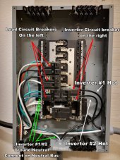
Lets use the pic of the main panel with cover off that you posted above. The bus bar tabs are arranged so they alternate and it doesn't matter if you install the 2 pole breakers across from each other, one on the top left and one on the top right or stacked on top of each other either on the left or right in the panel. (They should be installed either directly across from each other or stacked WITHOUT a space inbetween) This is were colors come in handy. By convention the bus bar on the left is L1, Black wires & the bus bar on the right is L2, Red wires. So get some Black and Red electrical phase tape and stick the correct color above each bus bar and note which pole of the 2 pole breaker is attached to each color. You could even put a Red piece on the pole of each breaker that is connected to the L2, Red bus bar.
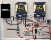
The inverter phases are as Follows: L1, Black is being produced by inverters #1 & #2 while L2, Red is being produced by inverters #3 & #4. So L1, Black from inverter #1 goes to L1, Black on one of the breakers and L1,Black from inverter #2 goes to L1, Black on the OTHER breaker. Same for L2, Red.
In the pic you posted there are 2 cables, they are both Communication (phase sync) cables not current sharing cables. Refer to the manual Pg 55. In your set up there are going to be 4 Communication cables daisy chained between all 4 inverters. There will also be 4 Current sharing cables, 2 between #1 & #2 (L1, Black) and 2 between #3 & #4 (L2, Red). Do Not use current sharing cables between phases.