diy solar

diy solar

48V 280Ah DIY battery

brum

Solar Enthusiast
Joined
Feb 8, 2022
Messages
495
Let the build begin!

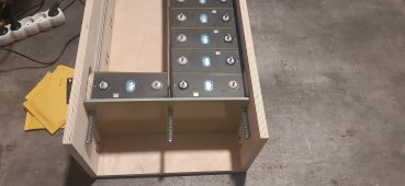
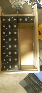
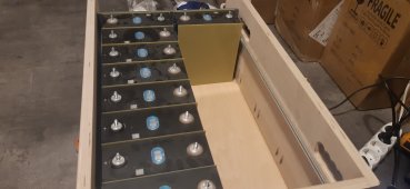
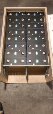
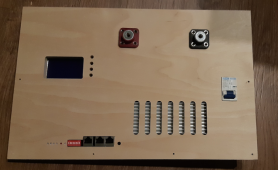
For several months I've been planning the storage for my solar system. The inverter is SMA Sunny Island. The battery will be a DIY 48V 16S LiFePO4 one. The design will be pretty similar to the Seplos Mason one. The main difference is that the enclosure will be from plywood and the cell compression will be done with springs.
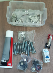
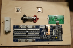
Here are the parts:
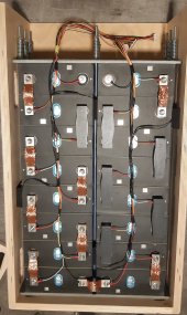
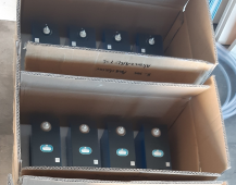
1) 16 280Ah CATL cells. These have been tested in the forum and should capacity close to 300Ah. Internal resistance on all cells is identical. This is all that I've tested till now.
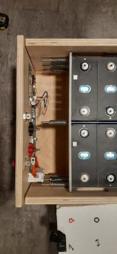
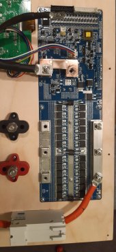
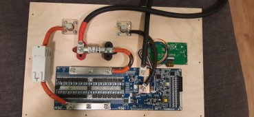
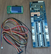
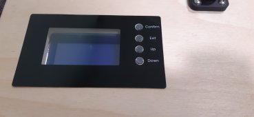
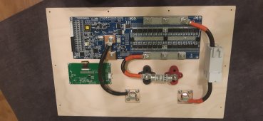
2) Seplos LiFePO4 150A 16S BMS.
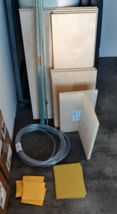
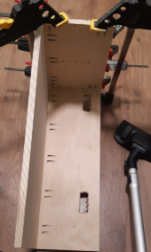
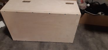
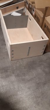
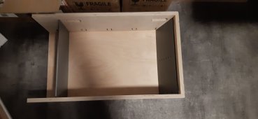
3) Plywood (missing on the picture) for the enclosure.
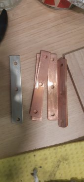
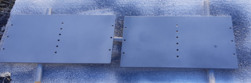
4) 6mm steel plates for compression. These have been laser cut and spray painted with zink spray.
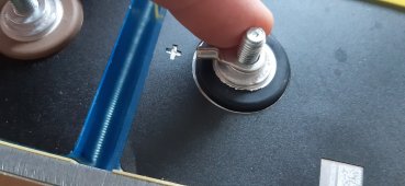
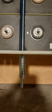
5) 6mm threaded rods, springs, and insulation tube for the compression force.
6) FR4 0.5mm sheets cut to the appropriate size (172 x 206 IIRC) on the CNC router for insulation between cells.
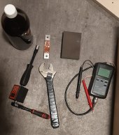
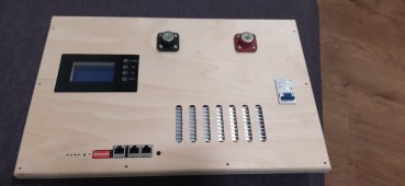
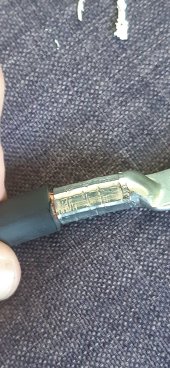
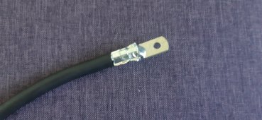
7) Lugs (JG type), fuse (Eaton 100FE), DC circuit breaker (TOB1Z-125), and battery terminals.

Some items are still missing:
1) Busbars still missing, but I'm expecting them to arrive in the next couple of days. Flexible braided busbars will be used.
2) Wires - welding cable or car audio power cables.
3) Heating wire. Likely this one from Aliexpress. 48V or 230V one. Haven't decided yet.

I'll document the process of building the battery with pictures to assist with ideas for future builds.

And the final touch will be WiFi connectivity. The Seplos serial protocol has been reverse-engineered and on GitHub there are projects using it. I'll use an ESP8266 module to enable the battery to connect to the WiFi, collect telemetry and send it to a telemetry DB. The module will also control the heating elements (I did not know Seplos have that ability until I got the BMS and saw the missing parts from the PCB).
 

Attachments

  • 1672053861861.png
    1672053861861.png
    373.7 KB · Views: 163
  • 1672053896389.png
    1672053896389.png
    388.7 KB · Views: 151
  • 1672053949505.png
    1672053949505.png
    318.5 KB · Views: 153
  • 1672053982412.png
    1672053982412.png
    477.6 KB · Views: 153
  • 1672054012536.png
    1672054012536.png
    457.4 KB · Views: 154
Last edited:
Minor progress today. I ran out of pocket hole screws. The handles and the back plate were machined. Once the case is ready the remaining will be built as close as possible to the final location. The battery will be close to 100kg and I want to reduce the transportation distance to its final location.
 

Attachments

  • 1672164609599.png
    1672164609599.png
    244.7 KB · Views: 62
The front panel has been machined. The second attempt produced satisfactory results. The display sits pretty deep and I may consider 3rd attempt, but not today. I'll upload the DWG file with the contours.

The circuit breaker and the communication ports are sitting flat on the panel. The LEDs are protruding just a bit. Access to the reset button is straightforward. To ease the access to the display buttons I'll use 3D-printed button extenders that will protrude a bit over the panel.
 

Attachments

  • 1672267010287.png
    1672267010287.png
    341.1 KB · Views: 146
  • 1672267237218.png
    1672267237218.png
    873.6 KB · Views: 141
The front panel is completed now. So is the case base.

I got a bit lazy and decided not to invest more time in improving the display location. It will stay 12mm below the panel surface. Instead, I invested a bit more time in improving the case by adding 70mm long coarse-thread screws. Now there are pocket hole screws, PVA glue, and the 70mm euro screws. This should hold the cells while moving the case.

I'm wondering a bit about what wire size to use for the internal wiring. Thinner wires are easier to work with. Thicker wires will result in a lower voltage drop. What I'm thinking is to use 2 x 10mm2 in parallel in all places. What are your recommendations for 75A peak / 63A continuous current?
 

Attachments

  • 20221229_192543.jpg
    20221229_192543.jpg
    126.4 KB · Views: 108
  • 20221229_192538.jpg
    20221229_192538.jpg
    123.8 KB · Views: 105
  • 20221229_192533.jpg
    20221229_192533.jpg
    203 KB · Views: 115
  • 20221229_192527.jpg
    20221229_192527.jpg
    150.8 KB · Views: 117
  • 20221229_172822.jpg
    20221229_172822.jpg
    115.6 KB · Views: 117
  • 20221229_172807.jpg
    20221229_172807.jpg
    98.5 KB · Views: 112
  • 20221229_172800.jpg
    20221229_172800.jpg
    160.3 KB · Views: 108
3 hours later and wiring issue is solved. I have some 20mm2 leftovers. The result is in the picture.

From the battery to the front panel the wires may be a bit thicker. 25mm2 or 35mm2. Depending on the remaining lugs and how the available wires will fit in them.
 

Attachments

  • 20221229_230338.jpg
    20221229_230338.jpg
    262 KB · Views: 155
And to share a little trick I have in case you are using the YQK-70 crimping tool from China. People usually have a hard time finding the proper die size.

In my case, I tried to crimp a 35mm2 cable with the 35mm die. The 25mm2 die was way smaller than needed, the 35mm2 was just a bit bigger than needed. A cooking aluminum foil did a pretty good job here. Folded several times and wrapped around the lug. The results can be seen in the pictures.
 

Attachments

  • 20221230_130356.jpg
    20221230_130356.jpg
    157.7 KB · Views: 136
  • 20221230_130228.jpg
    20221230_130228.jpg
    248.6 KB · Views: 133
  • 20221230_130506.jpg
    20221230_130506.jpg
    165.1 KB · Views: 136
  • 20221230_130400.jpg
    20221230_130400.jpg
    118.8 KB · Views: 137
I have one of them, does make you wonder why they can't just make them the correct size.

Nice build by the way.
I agree that at least some of the crimps in mine are also not correct. The other thing with mine is that the on/off is the wrong way round lol.
 
It seems to be a bit more complicated with the dies. Different cable lugs are having different tube wall thicknesses. If the SC cable lug fits OK in the 35mm die, then the JG one does not.

So there is no one 35mm crimp die that fits all 35mm lugs.

The progress has mostly stalled. Almost nothing was working yesterday due to the new year holidays and I failed to get the copper busbar for the BMS. I plan to use a 15mm x 3mm busbar along the 3 connection points for B+ and P+ of the BMS to distribute the current.
 
Here are the contours (drawings.zip) for the front panel and the required details to get them machined.

BMS outside area clearance depth - 2mm
BMS inside area clearance depth - 16mm
Display area clearance depth - 6mm
Fuse area clearance depth - 4mm
The others are just complete cutouts. I can provide .tap files, but AFAIK are usually machine specific and I'm not so sure if they can be used direclty on another machine.

And some spoilers (please, ignore the massive amount of dust on the cells). Threaded rods are covered with tubes to protect the cells. Separators fit pretty tight between the compression rods (the benefit of machining all details). 3 out of 12 springs and rods were only placed. The goal was to confirm that everything fits as designed.

I'll probably put a layer of PU lacquer on the enclosure to give it a layer of protection.
 

Attachments

  • drawings.zip
    30.1 KB · Views: 51
  • 20221231_174726.jpg
    20221231_174726.jpg
    261.5 KB · Views: 129
  • 20221231_174741.jpg
    20221231_174741.jpg
    91.4 KB · Views: 122
  • 20221231_174750.jpg
    20221231_174750.jpg
    179 KB · Views: 124
Where did you get your battery terminals? I’ve been looking for something similar.
 
The cells are in place now. Partially compressed because I failed to find the test results for the springs and I'll likely have to test them again. IIRC the numbers the compression force should be at ~210kg per cell row now. The important detail is that the front panel fits. I forgot about the threaded rods when I was drawing it, but luckily no issues popped up.

The balancing leads will be directly over the busbar. It happened that the balancing lug diameter is the same as the welded terminal base. I'll check the voltage drop on terminals with and without balancing leads and if I see some difference I may reconsider the approach.

Tomorrow I hope to get the braided busbars and the copper busbars for the BMS. This should be the last missing details. After that, I'll start charging and then balancing the pack.

And by the way - once I finish with the build, I'll share the plans and BOM with links to where I've ordered the parts. This should ease anybody who tries to duplicate the enclosure.
 

Attachments

  • 20230102_164724.jpg
    20230102_164724.jpg
    276.5 KB · Views: 98
  • 20230102_204842.jpg
    20230102_204842.jpg
    100.6 KB · Views: 88
  • 20230102_204847.jpg
    20230102_204847.jpg
    91 KB · Views: 99
  • 20230102_204914.jpg
    20230102_204914.jpg
    103.4 KB · Views: 101
Cell busbars will be here tomorrow. And since I didn't have much else to do I finished the front panel wiring.

The BMS terminal busbar is tin-plated 15x3mm copper piece. Not that tin plating would make much difference, but it was fun. One of the pictures shows the tinning process. Tap water with just a bit of salt, pure tin on the negative pole, a cleaned copper piece on the positive pole, and the RD6024 supplying 60V at 1.5A. Once the busbar is out of the jar I used baking soda to polish it.

Before assembly, all parts were cleaned with fine sandpaper and then with isopropyl alcohol. The shunt is bare copper, so I used the Ox-Gard anti-oxidant compound there. The torque is 4.5Nm on the 5mm bolts on the BMS and 6Nm on all other places. I don't want to risk stripping threads and this should be more than sufficient. The milliohm meter showed between 0.03mOhm and 0.05mOhm on all connection points.

But still - I'm close to 4mOhm on the front panel. The fuse is 1.5mOhm, the DC breaker is 1mOhm, and the shunt is 0.3mOhm. The remaining 1.2 comes from the wires and the connections. I was thinking about changing the fuse with a higher rating. 160A fuses are available, but I have no detailed specs for them and I prefer to stay on the safe side.
 

Attachments

  • 20230103_161232.jpg
    20230103_161232.jpg
    62.3 KB · Views: 115
  • 20230103_205135.jpg
    20230103_205135.jpg
    72.5 KB · Views: 101
  • 20230103_210000.jpg
    20230103_210000.jpg
    132.4 KB · Views: 111
  • 20230103_220038.jpg
    20230103_220038.jpg
    296.2 KB · Views: 118
Last edited:
Finally, the work week is over. And I manage to make some progress. Cell busbars and balancing leads are in place. Tomorrow I'm attaching the BMS, configuring it, and starting the balancing process.

All cell-to-cell connections are with resistance in the range of 0.16mOhm to 0.18mOhm.

The busbars that came with the cells are copper and non-flexible. Out of curiosity I tested two times connections with the stock busbars and got resistance in the range 0.21-0.22mOhm. The flexible ones are better.

There is a pretty nice advantage of the mesh wire busbars. They are so flexible that they can be used on the connection between cell 8 and cell 9.

The caps are used for a bit more protection while the battery is assembled and balanced. I'm not sure that I'll keep them after that. I'll share the STL file if somebody wants to use them. There are only a few of them in the picture because the others are still being printed.

Temperature sensors are also in place. Pads of microporous rubber pipe isolation are used to the sensors in place. This way they will measure the cell temperature, not the surrounding air temperature.

And the tools used in the process:
1) Digital torque gauge
2) Electrical tape isolated ratchet and spanner (spanner for holding the busbars while torquing them)
3) Abrasive block (abrasive sponge) for cleaning the busbars and the cell terminals
4) Isopropyl alcohol for wiping contact surfaces
 

Attachments

  • 20230106_211148.jpg
    20230106_211148.jpg
    154.4 KB · Views: 121
  • 20230106_205004.jpg
    20230106_205004.jpg
    546.8 KB · Views: 111
Back
Top