diy solar

diy solar

48V 280Ah DIY battery

And it is live!

I followed the commissioning procedure step by step. Disconnected AC side, connected DC side, and LAN cable. Connected the battery and the battery CAN cable. Started the DC side, go through the wizard, and finally click save. Then connected the AC breaker and ... nothing. The unit was up, but it was not generating any power. It was waiting for some permission.

Took me around 45 minutes to find out what was going on. Almost got a bold place on my head from scratching it. And finally, I clicked the "AC ON" button on the front panel. Something clicked and I heard buzzing noise. Grid - 2W, inverter 1kW.

The BMS CAN wiring was almost straightforward. Almost because the SMA folks are counting the RJ pin numbers on the socket, not on the plug. This leads to a pin mismatch and I managed to swap the CAN L and CAN H lines. Looked at the manual again and said - nope, no way the Seplos folks could have reversed the order of the pins. But swapped the CAN L and CAN H wires and suddenly the inverter showed 45% SOC for the battery.

The heat insulation sheets around the battery should keep it at >= 15C. There is a metal stand on the wall that should withstand the load. It was a decent challenge to put the battery up there. Ignore the fridge below :) . And the AC box - I just patched a connection point there and most of it will be rebuilt in the summer.
@brum , nice build!
If possible, please share the parameter file for your BMS battery settings.

We have a similar setup (with SMA SI5048) with an issue where the inverter shuts down whenever the grid disconnects/switch-off due to load-shedding.
The alarm shown on the BMS is SCP (short circuit protection).
I am still trying to don't understand the reason for this.
 
Last edited:
This is most likely related to the BMS settings. Try the Seplos BMS section for advice.

My battery inverter is currently off. It is too cold and there is no excessive energy.
 
@brum , nice build!
If possible, please share the parameter file for your BMS battery settings.

We have a similar setup (with SMA SI5048) with an issue where the inverter shuts down whenever the grid disconnects/swithc-off due to load-shedding.
The alarm shown on the BMS is SCP (short circuit protection).
I am still trying to don't understand the reason for this.
andy (off grid garage ) just posted a nice video explaining how the bms controls your inverter through canbus or rs485.
geared toward victron gear, but will apply to just about all
 
andy (off grid garage ) just posted a nice video explaining how the bms controls your inverter through canbus or rs485.
geared toward victron gear, but will apply to just about all
I only use voltage settings.
We have a similar setup (with SMA SI5048) with an issue where the inverter shuts down whenever the grid disconnects/swithc-off due to load-shedding.
The alarm shown on the BMS is SCP (short circuit protection).
I am still trying to don't understand the reason for this.
Have tried a few things but could not solve this yet. Beginning to think it is a faulty BMS issue.
 
Today the battery introduced a surprise. Suddenly I found out that no data is coming from the battery inverter for the last 5 hours. The quick check revealed a blown fuse.

The cells were disconnected from the BMS, took the front panel out, and did a careful inspection, but no issues except the blown fuse popped up. Changed the fuse, assembled it back and the battery was alive. Next step - check the inverter. Put the AC breaker to the off position, got the 60V power supply, set the limit to 2A, and started the inverter. No issues popped up, so I started the battery and connected the AC breaker. And everything worked normally.

Curious about what may have happened I decided to open the fuse. No signs of a surge there. No changed color of the internals, and no sign of issues. I've seen a blown fuse after a short circuit and that was not the case.

Now I'm curious about what may have happened. The load on the inverter was 2.4kW just before the issue and 0.5kW right after that. No power spikes, no fluctuation in the grid voltage, no nothing. The system has been working flawlessly for 4+ months and has been maxed out a lot of times with no issues. And now, with low load, the fuse died somehow...

The fuse was a Bussman 100FE from Aliexpress. IIRC something around 7-8 USD. Damn cheap, but I did some research and they had a factory in India. The prices there are several times lower compared to what we get in Europe. The fuse I put in its place is aR rated, 160A, some Chinese brand with no specs, but from what I've researched it should be good and provide 20+kA breaking capacity.
 
Yep, totally agree with you. But on the inside, it was looking quite genuine.

I'm moving to 125LET fuse. Again from Aliexpress, but 1:1 with what I'm finding as offers from reputable EU suppliers. There is likely no need for that and the existing 160A aR fuse will handle the short circuit situations, but somehow using a fuse with no clear specs makes me feel uncomfortable.
 
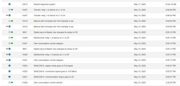
That's interesting. Right before the fuse cuts the battery I see some unexpected logs (18:55). These usually pop up after the inverter is started up (i.e. after a grid failure or manual restart). But there are no logs for grid failure this time. The fuse failed between 18:59 and 19:00, or 4 to 5 minutes after that.
 

Attachments

  • 1684349394912.png
    1684349394912.png
    111.8 KB · Views: 14
  • exported_data.zip
    2.7 KB · Views: 4
Based on the log, the fuse may have taken one for the team. In that case, I withdraw my thought that the fuse was poor quality. I would submit the log to the vendor's tech support and see what they can tell you.
 
Not yet. I'll think about it for a couple of days.

The BMS will cut the discharge path at 150A. The fuse will work at 150A for several minutes (if we accept that it was a genuine fuse). To be above 150A the only option seems to be a short circuit. And a short circuit would leave some marks. If it was the inverter, then it would not be working fine after that.

I'll look at the old logs to confirm that this is an exceptional case. I'll look also at the documentation for details on the event. Since this was like 5 minutes before the fuse failure I have some doubts that it is related. The event timestamps between the two systems have always been 1:1 till now, so I'm considering them correct. And I see no issues reported from the BMS (like spikes).
 
Last edited:
So one or other way I'll go through the SMA support. The inverter failed today. As it was working just fine suddenly popped up a Fault/Island Grid error. 2 hours later I saw increased gird consumption, found out the error and a disconnected circuit breaker. The surge protection devices were fine, the RCD was also fine.

Let's see what the SMA support will say on the problem. I'll share details once I have such. I hope that the tier 1 equipment support will be smooth.
 
False alarm. The inverter is fine. It has gone into some error mode due to AC overvoltage. I suspect that this was related to a storm that was going on around the time when the error has triggered.

The short on the AC2 out was due to a relay staying on. The relay is between the transformer and the AC. A toroidal transformer is drawing massive current when initially connected. I recall doing a pre-charge circuit for a 300W transformer that was tripping a 16A breaker 15 years ago. The inverter is capable of more than a 5kW peak, so its transformer is 3+kW. This can easily trip the 20A/B breaker that is in front of the inverter.

The short was gone after the inverter stayed off for some time. And I started building up the puzzle. The chain of events is something similar to that:
1) AC overvoltage (reason unknown, but possibly due to a thunderstorm that has not burned out any of the surge protectors). Inverter showed error 1707 - AC1 overvoltage.
2) Inverter goes into some fault mode saying it is in island mode but was not producing power. Despite that, it kept the transformer connected.
3) Restart of the inverter (shutdown procedure, disconnecting the AC side, disconnecting the DC side) has resulted in the inverter being in an off state, but the relay between the transformer and the AC stays on. Probably a firmware bug or design flaw.
4) Once I tried to connect the AC side the breaker tripped. There is a massive toroidal transformer that is not energized and is being directly connected to the AC. This probably can bring down the 63A main breaker too.
5) Due to the relay being connected, the AC side showed a short circuit (or almost a short circuit).
6) After being off for some time the relay has reset to off state. How - now idea. But after a few hours, everything works fine again.

And now on the bug/design flaw - it would be impossible to reconnect the AC side with the relay being in that state. When the inverter is on and is connecting the grid it first syncs the output to the grid and then connects the AC side. In an off-grid setup, the inverter starts first, so it would not be an issue.
 
So this is getting stranger ant stranger. There is regular flow when the battery gets full, the inverter starts to discharge it and after a few seconds there is voltage spike according to the inverter.

From what I see the spikes are to over 65V in some cases and when this happens the inverter goes in failure mode.

Here are the logs from yesterday. The inverter was charging, the SOC was going up, it got to 100% and shortly after that the inverter stopped charging. Then it started discharging, the battery voltage measured by the inverter was 56.7V - 56.8V, the voltage was dropping to 56.3 and there was a spike of 61.2V for 3 seconds. Than back to 56.2V and a few seconds later a spike to 65.2V. Shortly after that the inverter goes in fault mode and the battery voltage is 55.7V.
 

Attachments

  • Sunny_Island_4.4M_13_3015093673_short.csv.zip
    4.3 KB · Views: 7
So this is getting stranger ant stranger. There is regular flow when the battery gets full, the inverter starts to discharge it and after a few seconds there is voltage spike according to the inverter.

From what I see the spikes are to over 65V in some cases and when this happens the inverter goes in failure mode.

Here are the logs from yesterday. The inverter was charging, the SOC was going up, it got to 100% and shortly after that the inverter stopped charging. Then it started discharging, the battery voltage measured by the inverter was 56.7V - 56.8V, the voltage was dropping to 56.3 and there was a spike of 61.2V for 3 seconds. Than back to 56.2V and a few seconds later a spike to 65.2V. Shortly after that the inverter goes in fault mode and the battery voltage is 55.7V.
are you using voltage on your inverter, or actual communication ( not sure if that is even possible on a sunnyisland)
 
Actual communication. The inverter is using lithium battery and is getting the SOC from the BMS. The BMS is Seplos 150A, last generation.
 
So this is getting stranger ant stranger. There is regular flow when the battery gets full, the inverter starts to discharge it and after a few seconds there is voltage spike according to the inverter.

From what I see the spikes are to over 65V in some cases and when this happens the inverter goes in failure mode.

Here are the logs from yesterday. The inverter was charging, the SOC was going up, it got to 100% and shortly after that the inverter stopped charging. Then it started discharging, the battery voltage measured by the inverter was 56.7V - 56.8V, the voltage was dropping to 56.3 and there was a spike of 61.2V for 3 seconds. Than back to 56.2V and a few seconds later a spike to 65.2V. Shortly after that the inverter goes in fault mode and the battery voltage is 55.7V.
Same case with me, i use battery lifepo4 15s, and i use mode VRLA 46V. They can spike up to 60V
Has your problem been solved? If so, what settings did you change?
 
Yes, it is solved. The BMS should not disconnect the charging path. If it does - find out why and fix it. If it doesn't - there is no reason for such voltage spikes.
 
Yes, it is solved. The BMS should not disconnect the charging path. If it does - find out why and fix it. If it doesn't - there is no reason for such voltage spikes.
Ok i know, can u please share parameters for charger?
 
Back
Top