diy solar

diy solar

48v System Wiring Check - Help Please!

CarlCruzin

New Member
Joined
Oct 14, 2020
Messages
90
Location
Nevada
I've put this project on the back burner for a while because I was a bit overwhelmed, but I'm trying to finally tackle it...
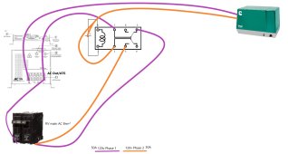
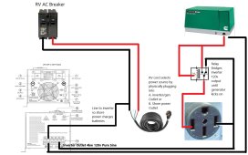
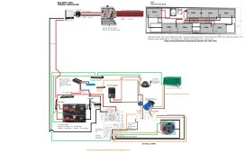
So I did my best to make a "wiring diagram" on paint with my components. This is just to draw out the idea and work out the kinks. Would those experienced and knowledgeable mind looking it over to make sure I'm not missing anything big? Or to offer alternatives?

A couple design considerations & compromises:
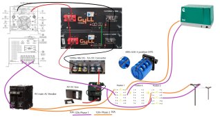
1. I purchased a single phase 120v output 4kw 48v Inverter/Charger/ATS and it only has a 40A bypass. Because of this, on both transfer switch options, one leg goes through the inverter/charger on the way to the breaker, and the second leg goes straight to the breaker.
1.1. Problem: When the generator is not running, only one of the legs will be powered. Is there a way to split the inverter output when the generator is not running, and not split when it is?

2. I intend to replace my coach batteries and eliminate the existing converter with this system, and my hydraulic levelers are on a 100A breaker, so I got a 100A DC-DC converter to power all things 12v

3. I intend to add solar later, but for now I will be charging via shore power
 

Attachments

  • RVWiringDiagram_RoughDraft.jpg
    RVWiringDiagram_RoughDraft.jpg
    198.3 KB · Views: 51
Last edited:
Hello..

I guess I'm trying to wrap my head around the issue your describing in 1. and 1.1, on why only one of the legs will be powered.

First let me post a picture of the factory wiring on my Safari Motorhome, and see if we can figure out a good way to help here (click on it for larger view). I actually like the way Safari wired it up (for the factory scenario anyways).

1641531617289.png

On my motorhome, if you see the PS-250 indicated there, it is a standalone ATS, equivalent to your manual switch selector, for your shore power / Onan switchover. Mine is fully automatic, when I start the generator it automatically switches from cord to Onan without user intervention, this handles all wires on switchover.

You can see the power cord going into top-right on the PS-250 (it is a standard 50a RV cord with 240v, 2 hot legs, neutral, and a ground), Onan is coming in on bottom-right of the PS-250 (with 2 hots, and a neutral), and then out the left-top of the PS-250 is the shore/gen AC goes over to the left AC Breaker labeled '2' and '3' on the diagram (2 hot legs still, the diagram shows it like single wire, but is really two wires, black and red), then the leg labeled '2', goes to the middle breaker labeled '5A/B, which goes to the inverter 'INPUT' (30a), let's just pretend it is a 48v inverter here (doesn't really matter anyway for this discussion).

Then the inverter AC has a couple outputs that go out of it to the dedicated inverter circuits it manages.

Going back to the breaker box again, the other leg of that left input breaker labeled '3' feeds the other breaker circuits that will not go through the inverter AC circuits.

Perhaps you could clarify if you are wanting to be running all AC power through your inverter, or using one leg to run inverter AC and other leg to run non-inverter circuits, like commonly done on many RVs. What will be your RV input cord configuration?

As you can see, not all AC circuits go through the inverter. I guess I'm trying to figure out why you are routing the AC coming out of your inverter, going back over to your manual switchover selector again. Can't you run that over to your breaker feeds for your inverter-only AC circuits?

1641532920324.png

Perhaps you could explain a bit more to help me understand?

So whether or not my Onan is running, or is on shore power, one leg goes to the inverter, and other one goes directly to my breaker panel bypassing the inverter (to run heavy load items like the big roof AC units and such).

So my assumption here, is you want to be able to install another (3rd) ATS or manual selector switch in somehow so you can include all the circuits that the generator / shore power normally run while they are online? So when they are offline, you can switch them to also be on the inverter?

Or is it something else?
 
Last edited:
Hi Samsonite, Thank you for taking the time to respond. That is great that you have an AC diagram. I have reached out to my warranty rep to see if he will send me one.

My inverter is 4kw pure sine, and the battery pack is 10kwh. I have chosen these capacities with a goal to offer the convenience of AC power usage with minimal generator interruption. Once I install a decent amount of solar, hopefully no need for the generator use.

My intention is to wire the RV so everything can be run off of the inverter. I wouldn't run both air conditioners at the same time, but may want to run one or the other at different times. I plan on switching off the AC breaker to the fridge and water heater so they don't use up the battery when I'm not on shore power.

I would prefer to utilize the auto generator start feature of the inverter, so the battery pack can be recharged once depleted. The only way I can think of accomplishing that goal is for the "Phase 1" inverter output leg be run to both of the 50A breaker inputs. Then once the generator starts up, it disconnects that second leg of "Phase 1" power so it doesn't touch the "Phase 2" power that will be coming in with the generator. I might just need to give up on the AGS, and do the switch manually...
 
The wiring to your battery is inefficient. A diagonal connection will draw from both batteries better but it's still not ideal. If that was my system, I would run equal length cables from each battery to a bus bar. The all other connections (inverter, 48v-12v converter) attach to the bus bars.
 
The wiring to your battery is inefficient. A diagonal connection will draw from both batteries better but it's still not ideal. If that was my system, I would run equal length cables from each battery to a bus bar. The all other connections (inverter, 48v-12v converter) attach to the bus bars.
There is a communication cable between them that I believe balances charging and discharge
 
Hi Samsonite, Thank you for taking the time to respond. That is great that you have an AC diagram. I have reached out to my warranty rep to see if he will send me one.

My inverter is 4kw pure sine, and the battery pack is 10kwh. I have chosen these capacities with a goal to offer the convenience of AC power usage with minimal generator interruption. Once I install a decent amount of solar, hopefully no need for the generator use.

My intention is to wire the RV so everything can be run off of the inverter. I wouldn't run both air conditioners at the same time, but may want to run one or the other at different times. I plan on switching off the AC breaker to the fridge and water heater so they don't use up the battery when I'm not on shore power.

I would prefer to utilize the auto generator start feature of the inverter, so the battery pack can be recharged once depleted. The only way I can think of accomplishing that goal is for the "Phase 1" inverter output leg be run to both of the 50A breaker inputs. Then once the generator starts up, it disconnects that second leg of "Phase 1" power so it doesn't touch the "Phase 2" power that will be coming in with the generator. I might just need to give up on the AGS, and do the switch manually...

So say if you had a wiring, similar to mine to start with. There is an ATS built into the inverter, leave that for shore/Onan AC power (off primary leg), battery charging, vs inverter-output only ATS switching, and mine has the other standalone ATS which is only in charge of automatic 'cord vs Onan' switching only.

Then I could add a 3rd standalone ATS that is wired only for post-inverter (output) switching, to 'bridge-in' the inverter AC output to the secondary leg breaker-set. And we want to make sure that it is only to connect to the secondary leg breakers, we don't want to bridge to the primary leg input circuit for the inverter (that's why those 2 circuits should stay separated normally)...

This is why if you had 3 sets of breakers, a pre-breaker with both legs, one going to inverter input and other feeding the secondary leg breakers, and the inverter output going to another group of breakers (that it will always power). And essentially the 3rd ATS would disconnect the secondary leg breakers from its normal input bus (shore / Onan), and connect it to the AC output circuit on your inverter, so they would all be combined on that output.

ATS signaling is the other aspect. So when the generator is off (and shore power cord is disconnected), the 3rd ATS would be in normal relaxed position to connect secondary leg breaker circuit to the output of the inverter. Then when generator starts (Onan waits several seconds to stabilize RPM before it applies AC), once Onan applies the AC power, it signals 3rd ATS to change/close, switching to disconnect the secondary leg breakers from inverter output circuit and go back over and reconnect them to their normal AC input bus (shore/Onan)...

Shore power would also be the same AC trigger to signal the ATS to switch and run same like it would if the Onan was running, so if the cord was plugged in it would run secondary leg of cord and not on inverter power.

This way of switching with a 3rd ATS doesn't put any short-circuit risk, as the secondary leg breakers would have to disconnect from one to be connected to the other, but never to both at same time.

The whole setup would be fully automated.
 
Last edited:
So say if you had a wiring, similar to mine to start with. There is an ATS built into the inverter, leave that for shore/Onan AC power (off primary leg), battery charging, vs inverter-output only ATS switching, and mine has the other standalone ATS which is only in charge of automatic 'cord vs Onan' switching only.

Then I could add a 3rd standalone ATS that is wired only for post-inverter (output) switching, to 'bridge-in' the inverter AC output to the secondary leg breaker-set. And we want to make sure that it is only to connect to the secondary leg breakers, we don't want to bridge to the primary leg input circuit for the inverter (that's why those 2 circuits should stay separated normally)...

This is why if you had 3 sets of breakers, a pre-breaker with both legs, one going to inverter input and other feeding the secondary leg breakers, and the inverter output going to another group of breakers (that it will always power). And essentially the 3rd ATS would disconnect the secondary leg breakers from its normal input bus (shore / Onan), and connect it to the AC output circuit on your inverter, so they would all be combined on that output.

ATS signaling is the other aspect. So when the generator is off (and shore power cord is disconnected), the 3rd ATS would be in normal relaxed position to connect secondary leg breaker circuit to the output of the inverter. Then when generator starts (Onan waits several seconds to stabilize RPM before it applies AC), once Onan applies the AC power, it signals 3rd ATS to change/close, switching to disconnect the secondary leg breakers from inverter output circuit and go back over and reconnect them to their normal AC input bus (shore/Onan)...

Shore power would also be the same AC trigger to signal the ATS to switch and run same like it would if the Onan was running, so if the cord was plugged in it would run secondary leg of cord and not on inverter power.

This way of switching with a 3rd ATS doesn't put any short-circuit risk, as the secondary leg breakers would have to disconnect from one to be connected to the other, but never to both at same time.

The whole setup would be fully automated.
Forest River got back to me and said they don't keep an AC input and wiring diagram... :-/

I don't believe my RV has a transfer switch from the factory. In order to run off the generator, I have to plug my shore power cable into an outlet in the same storage area.
 
Forest River got back to me and said they don't keep an AC input and wiring diagram... :-/

I don't believe my RV has a transfer switch from the factory. In order to run off the generator, I have to plug my shore power cable into an outlet in the same storage area.

Ok so that isn't a big deal, it just means there would be 2 ATS (inverter ATS functionality and a second ATS you'd install post-inverter AC output vs secondary leg) instead of three, since your cord vs generator selection is manual. If you ever decided later, you could even put one in on that too if you really wanted to...
 
Ok so that isn't a big deal, it just means there would be 2 ATS (inverter ATS functionality and a second ATS you'd install post-inverter AC output vs secondary leg) instead of three, since your cord vs generator selection is manual. If you ever decided later, you could even put one in on that too if you really wanted to...
I guess I need to better understand how to wire an ATS. It sounds like relays with a logic board?

After some research, what comes to my mind for handling the power paths is a DPDT relay/Contactor where one is normally closed and the other is normally open?

I drew up what I think I'm describing:
1. Phase 1 is run to the Inverter/charger/ATS, where the output is tee'd, running directly to one leg of the 50A breaker, the other to a normally closed terminal, which sends it to the other leg of the 50A breaker.
2. Phase 2 is run to the relay coil as well as the normally open terminal.
3. When the generator kicks on, it will energize the relay and simultaneously disconnect the phase 1 tee'd line from the second breaker leg and connect phase 2 to the second breaker leg.
 

Attachments

  • DPDT.jpg
    DPDT.jpg
    113.2 KB · Views: 4
Yeah, sounds like you're getting the concept alright now, an ATS relay looks something like this:

1641621880554.png

Remember that these types of switches have a 'A' and a 'B' and a 'Common' (for each of 2 channels). My thought was to wire the relay in the direction so the 'Common' goes to the secondary leg breaker, so it can toggle A or B between inverter and generator (respectively)... Then you could do what you wanted with the other conductor channel (or just leave it empty).

Or maybe your way was better based on the way you have the 2 breakers configured in your scenario (since I may not have interpreted what you were exactly articulating in that picture and based on your RV). Anyways, you get the idea.


More ATS units.
Ref:
 
Last edited:
I did some looking around and actually found some perfect unused space under the master bed, along with most of the AC & DC wiring.

At this point given the setup of my RV, I'm thinking if I try and approach this with the K.I.S.S. method, I can splice the generator outlet with the DPDT relay/contactor similar to the prior diagram with the inverter. I figure since I will need to access the shore cable for either power source, an ATS will not benefit me much in terms of switching between shore power or generator power.

A. Shore cable plugged into generator/inverter output:
1. When the generator is not running, the inverter 120v single phase output will be bridged to both hot legs of the outlet, powering both AC breakers, and potentially the whole RV
2. When the generator turns on, it will terminate the inverter outlet bridge, and power one AC breaker directly with one phase, and the other through the Inverter's pass through transfer switch (while also charging the battery pack)

B. Shore cable plugged into shore power:
1. Shore powers both breakers as normal.
2. 120v line run to inverter so it can charge the battery pack
 

Attachments

  • 20220108_111102.jpg
    20220108_111102.jpg
    252.8 KB · Views: 5
  • 20220108_111201.jpg
    20220108_111201.jpg
    376.8 KB · Views: 5
  • 20220108_111157.jpg
    20220108_111157.jpg
    243.4 KB · Views: 5
Here is my updated diagram. How does it look?
 

Attachments

  • ACWiringDiagramWithRelay.jpg
    ACWiringDiagramWithRelay.jpg
    180.5 KB · Views: 7
While I'm not familiar with that line of batteries, I don't think communication is going to cut it.
I was able to confirm what you recommended. The manual states to use equal length wires from each battery to a buss bar. Thank you.
 
Finalized diagram with solar
 

Attachments

  • ACWiringDiagramSinglePhaseGenWithMTS.jpg
    ACWiringDiagramSinglePhaseGenWithMTS.jpg
    168.7 KB · Views: 9
Back
Top