diy solar

diy solar

4S2P Battery pack project

waiapasi2006

New Member
Joined
Mar 27, 2021
Messages
51
Hello all.
I got these battery in from the long waiting list.....
These are 230AH eve Cells. A total of 8.
I had top balanced the cells to 3.65 v and built a single 4S pack for testing their capacity.
This is what I have below. I did build a small box to help keep the cells intact.
Yes, did stick them in a milk crate for easy transportation.

230 AH BAT BOX.JPG

230 AH BAT_BMS.JPG

230 AH BAT_BMS 2.JPG

230 AH BAT_BMS_INVERTER.JPG

My test at first.
used a heat gun.
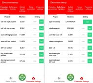
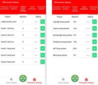
What threw me off was the 13A on the heat gun vs. what the Dally app was showing 130.7A.
The wat meter showed 1428 watt pulled from the inverter and the clamp meter 130.6A ( Almost the same from the dally mobile app)
I ran this test for about 10 minutes to see if the inverter will hold up.

My question,
Why is the Dally app showing 130.7A vs 13A?

POWER  AND AMP COMPARISON.JPG


But, I was surprised that everything was cold to the touch.

Edit: Thanks to Forum and everyone here I was able to take on this project!
 
Last edited:
That is correct. Amps X volts = watts and the heat gun runs off watts:

=================

120 volts 13 amps = 1560 wats

12 volts X 130 amps - 1560 watts

12 volts X 12 amps = 156 watts

===================

EDIT: Seems a little off still. THe inverters I use have 15% losses, so you are showing very, very low losses, <1%. I would think the heat gun shows 13 amps, the inverter would push that out by pulling the 130 amps it needs from the battery pus another 15% (20 amps), so I would think the Daly shows 150 amps.

Second Edit: I have not done much “heat“ testing, but I run thick 4/0 wires for 155 amps for a coupe of minutes, and those wires do not get hot. If I dropped this down to 2 AWG, I think it would. 2 AWG is not rated for that much amperage.
 
Last edited:
To run a long term load on the same 4S battery, I charged them back up to 14.6V.
My second test was using my refrigerator.
The spec:
REFRIGERATOR SPEC.JPG

Inverter used with the same cheap wires:

20210919_153531.jpg

These are the number I got as far as capacity goes for this set of battery.
Time: 29:12 Hours
Amp: 9.7
KW: 2.45 per meter.

Fridge test.JPG
 
Last edited:
That is correct. Amps X volts = watts and the heat gun runs off watts:

=================

120 volts 13 amps = 1560 wats

12 volts X 130 amps - 1560 watts

12 volts X 12 amps = 156 watts

===================

EDIT: Seems a little off still. THe inverters I use have 15% losses, so you are showing very, very low losses, <1%. I would think the heat gun shows 13 amps, the inverter would push that out by pulling the 130 amps it needs from the battery pus another 15% (20 amps), so I would think the Daly shows 150 amps.

Second Edit: I have not done much “heat“ testing, but I run thick 4/0 wires for 155 amps for a coupe of minutes, and those wires do not get hot. If I dropped this down to 2 AWG, I think it would. 2 AWG is not rated for that much amperage.

Second Edit: I have not done much “heat“ testing, but I run thick 4/0 wires for 155 amps for a coupe of minutes, and those wires do not get hot. If I dropped this down to 2 AWG, I think it would. 2 AWG is not rated for that much amperage

= At the time of testing the Pack, that was the only item that came to mind. I will definitely change those cheap wires that came with the inverter.
Still a work in progress.

I appreciate your feedback Chrisski.
Thank you.
 
Last edited:
I still check voltage loss when I put wires on inverters and Batteries, but I have never found that to matter. I just make sure the wires can handle the ampacity. Recommend wiring for the lowest voltage of the system. TEsting we usually do is when the batteries are charged, but battery amperage skyrockets when the battery drifts towards the low state. 2.5 volts per cell comes out to a 10 volt battery. My 12 volt inverter has a 10.5 VDC low voltage cutoff. THat 2000 watt inverter could see 230 amps in that case. THat same 2000 watt inverter would Normally would be 180 amps on a full battery with float set proper.

THere’s lots of charts out there some better, and wire ratino as published by the manufacturer will trump this, but this is what I use for wire ampacity:

3E2B9381-F2B5-4E07-8C85-906C6890D98A.jpeg
On a side note, those are the very same tiles in my kitchen. I would not be surprised if you are in central AZ also,
 
Second Edit: I have not done much “heat“ testing, but I run thick 4/0 wires for 155 amps for a coupe of minutes, and those wires do not get hot. If I dropped this down to 2 AWG, I think it would. 2 AWG is not rated for that much amperage

= At the time of testing the Pack, that was the only item that came to mind. I will definitely change those cheap wires that came with the inverter.
Still a work on progress.
I appreciate your feedback Chrisski.
Thank you.
According to this reference a 2 awg wire would be in the neighborhood of 140F with sustained 155 amps.
140F water is near enough to scalding.

 
I still check voltage loss when I put wires on inverters and Batteries, but I have never found that to matter. I just make sure the wires can handle the ampacity. Recommend wiring for the lowest voltage of the system. TEsting we usually do is when the batteries are charged, but battery amperage skyrockets when the battery drifts towards the low state. 2.5 volts per cell comes out to a 10 volt battery. My 12 volt inverter has a 10.5 VDC low voltage cutoff. THat 2000 watt inverter could see 230 amps in that case. THat same 2000 watt inverter would Normally would be 180 amps on a full battery with float set proper.

THere’s lots of charts out there some better, and wire ratino as published by the manufacturer will trump this, but this is what I use for wire ampacity:

View attachment 70726
On a side note, those are the very same tiles in my kitchen. I would not be surprised if you are in central AZ also,
Yes, I downloaded the wire chart as a refence from the resources tab.
Based on the parameters of the Dally setting, that is what I see here as well.
 

Attachments

  • DALY SETUP.JPG
    DALY SETUP.JPG
    97.6 KB · Views: 3
  • DALY SETUP2.JPG
    DALY SETUP2.JPG
    83.4 KB · Views: 3
To add to this. I went ahead and made some busbars with some copper pipes I had laying around.
1/4" pipes flatten down. Not my best handy work at the first attempt.
I ran on those busbars on the batteries for 29+ hours to power the refrigerator. I checked in on them from time to time while running and they were cold to the touch.
I didn't see a draw of more than 10A per the dally app and the watt meter which could be the case. The inverter was warm, but I could leave my hands on the surface with no problem.

20211017_184352.jpg
20211017_184413.jpg

20211023_121452.jpg
 
My plan now is to finally build the 4s2p packs in a box.
looking at 460A pack @ 12V (14.6V charged)
Should I double on the busbars I made?
Thank you.
 
My plan now is to finally build the 4s2p packs in a box.
looking at 460A pack @ 12V (14.6V charged)
Should I double on the busbars I made?
Thank you.
I saw a 2000 watt inverter in your pic.
If that is the only load...
2000 ac watts / .85 conversion factor / 10 volts low cutoff = 235.294117647 service amps.
235.294117647 / .8 fuse headroom = 294.117647059 fault amps.

There are tables online for copper busbar dimensions by heat and ampacity.

 
Note that heat shrink on the bars decreases their ability to dissipate heat.
 
I saw a 2000 watt inverter in your pic.
If that is the only load...
2000 ac watts / .85 conversion factor / 10 volts low cutoff = 235.294117647 service amps.
235.294117647 / .8 fuse headroom = 294.117647059 fault amps.

There are tables online for copper busbar dimensions by heat and ampacity.

Hello smoothjoe.
I did download most of these needed information from the resource tab. I just have to incorporate them now.
I appreciate your feedback.
Than you.
 
Back
Top