Xuba has to be making a killing, just on orders from forum members.
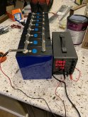
Have fun with the cells.
Have fun with the cells.


Actually I bought mine from ShenzhenLuyuanTechnologyCoXuba has to be making a killing, just on orders from forum members.
Have fun with the cells.
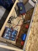
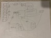
") You don't want it 90°. The fins on the back need to allow heat to go UP the fins.
You don't want it 90°. The fins on the back need to allow heat to go UP the fins.For the victron, that’s an easy fix, thanks for Pointing that out!I think Victron specs the installation of their MPPT as being in the vertical position. The "other" vertical position.
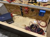
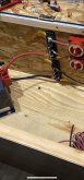
On the cable between your switch and the circuit breaker, the mounting points are at different heights. If you rotate the lug 180° on the cable you gain about 1/2", which may allow your cable to be level instead of at an angle. If you leave it an angle, there is stress on the stud where the lug is attached.
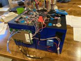
I left the battery connections until the very end. That way, when I fumbled something, it was no harm, no foul.
How easily can you source the fuses if one blows while you're traveling?I bought them from amazon.
Amazon.com: Blue Sea 5196 Fuse Block MRBF 3Circ Common: Automotive
Buy Blue Sea 5196 Fuse Block MRBF 3Circ Common: Fuse Boxes - Amazon.com ✓ FREE DELIVERY possible on eligible purchaseswww.amazon.com
How easily can you source the fuses if one blows while you're traveling?