diy solar

diy solar

6KW DIY Solar System Installation

Solar_Newbie

New Member
Joined
Oct 19, 2020
Messages
8
Good Day folks,
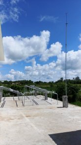
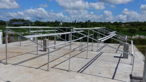
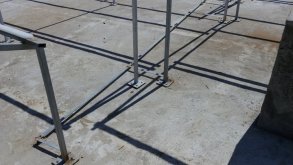
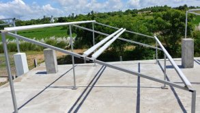
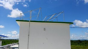
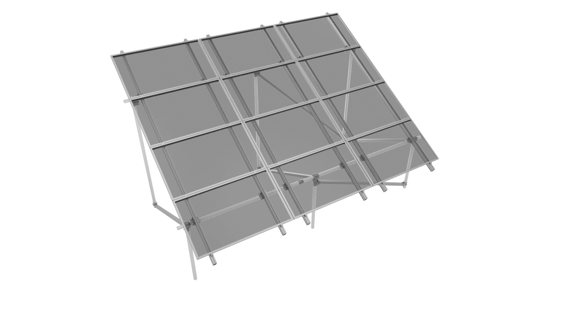
First of all greetings to all. I am installing a 6KW Off-Grid system in my farm due to non-availability of grid. I have purchased a system of 7.5KVA/6KW Inverter, 8 Nos. of 150 Ah batteries and 20 solar panels of 330W power each. I have installed the mounting structure with the correct angle and all. I just want to confirm that my panel connections to the inverter is ideal or not. Or is there any other setup which would provide better efficiency/power. I would hugely appreciate your help on this.

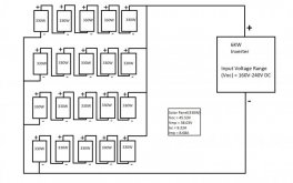
The Polycrystalline panels are rated at 330W(24V) and have the technical details:
(Vmp) - 38.03V
(Voc) - 45.23V
(Imp) - 8.68A
(Isc) - 9.22A

I have attached the technical details PDF of the inverter. It is the NXT+ 7.5KVA model. The inverter has an Input Voltage Range (Voc) of 160V-240V.
I have made a rough diagram of the system in Paint, at least with what limited knowledge I have. The reason for 5 panels in series according to me is because Voc of single panel is 45.23V and the input range of Inverter is 240V max. So in order to keep the input volatge below 240V I took 5 panels in series and then joining 4 such series connections in parallel making a total of 20 panels.
Am I correct in choosing this setup or am I doing something wrong? Appreciate all your help. Thank you.
 

Attachments

  • Luminous NXT 7.5(1).pdf
    777.6 KB · Views: 8
  • System.jpg
    System.jpg
    40.7 KB · Views: 12
I think I would keep it to 4 in series. then 7 parallel.
Voc x 5 x 1.2 =271 volts may be more than NXT would like to see. x1.2 is low temperature correction.

They seem to be leading you in this direction:
1603123096110.png 4 series / 5 parallel
 
Data sheet looks to me like it says 240 Voc max, 120 Vmp min
Do NOT connect 5 PV panels in series because they will come to 226V on a nominal 25 degree C day, but about 15% higher on a cold day, possibly destroying the inverter.
The PV panel will have a temperature coefficient of Voc (typically on data sheet but not on label), something like -0.4%/degree. You need to adjust Voc based on record cold temperature.
 
I think I would keep it to 4 in series. then 7 parallel.
Voc x 5 x 1.2 =271 volts may be more than NXT would like to see. x1.2 is low temperature correction.

They seem to be leading you in this direction:
View attachment 25356 4 series / 5 parallel
Did you mean 4S5P? An where did you get this PNG from? Kindly send the link.
 
Data sheet looks to me like it says 240 Voc max, 120 Vmp min
Do NOT connect 5 PV panels in series because they will come to 226V on a nominal 25 degree C day, but about 15% higher on a cold day, possibly destroying the inverter.
The PV panel will have a temperature coefficient of Voc (typically on data sheet but not on label), something like -0.4%/degree. You need to adjust Voc based on record cold temperature.
My place is near the sea and the lowest temperature we get is 16 degrees C and that too a few days at night. Daytime temperature throughout the year is almost always more than 25 degrees C. From Feb to December we almost have temperatures more than 35 degrees C. Do you also think that I should go with 4S5P?
 
If 16C is the record cold, never in the history of mankind has frost ever appeared on the ground, then voltage would only go higher than label Voc by 3% and you're OK.

In other news, once in 10 years San Jose gets enough of a freeze to burst pipes. Once in 50 years we get a tornado.

Any reason not to do 4S5P? Costs a little bit more copper wire, but is completely safe.
You have more than 2P, so put a DC rated breaker or fuse in series with every string. Value as shown on label of panel, voltage handling sufficient for string Voc.

Looks like you're in a 230V, 50Hz area?
 
I copied it from your post #1; reading and comprehension are important.
Haha don't know how I missed that. I'll go with 4(S)5(P) setup. Besides my panel frames are also built to support 4 panels each. So it should be good for wiring too. I'll post some pictures of the frame setup below.
 
If 16C is the record cold, never in the history of mankind has frost ever appeared on the ground, then voltage would only go higher than label Voc by 3% and you're OK.

In other news, once in 10 years San Jose gets enough of a freeze to burst pipes. Once in 50 years we get a tornado.

Any reason not to do 4S5P? Costs a little bit more copper wire, but is completely safe.
You have more than 2P, so put a DC rated breaker or fuse in series with every string. Value as shown on label of panel, voltage handling sufficient for string Voc.

Looks like you're in a 230V, 50Hz area?
Thanks, I'll go with 4(S)5(P) setup. Yes, The mains support 240V, 50Hz here in India.
 
I have the 6KW system on the 1st Floor terrace and another 3KW system on the 2nd Floor terrace as a backup. Here are some of the pictures, hope it helps someone. The frames are at a tilt of 19-20 degrees facing towards South since my latitude is 19.4 degrees.
I have used some foam for insulating the solar panels from the frames. The frames are grounded by GI flats. I have also installed a Lightning Arrester as we get frequent thunderstorms and cyclones here. This arrester is also grounded by using GI flats.

I am planning to use 6 sq. mm. DC cables to do the series connections and use 10 sq. mm. cable to take the parallel connections to the Inverter. Is this cable selection good? I'll try to find the correct fuse for the series connections as suggested above. Thanks.
 

Attachments

  • 20201020_120613.jpg
    20201020_120613.jpg
    90.6 KB · Views: 4
  • 20201020_120634.jpg
    20201020_120634.jpg
    73 KB · Views: 4
  • 20201020_120650.jpg
    20201020_120650.jpg
    74 KB · Views: 5
  • 20201020_120703_HDR.jpg
    20201020_120703_HDR.jpg
    87.4 KB · Views: 5
  • 20201020_120714.jpg
    20201020_120714.jpg
    36.6 KB · Views: 5
I have also installed a Lightning Arrester as we get frequent thunderstorms and cyclones here. This arrester is also grounded by using GI flats.
"Here are some of the pictures"
No pictures there!

What model lightning arrestor, and where in the system is it wired? (AC or DC, across which wires?)

I've performed low current hi-pot tests of some devices.

For those of us with grid-tied systems, utility lines are most likely source of surges. You're off-grid so that isn't your situation. Excluding direct lightning strikes, inductive coupling from nearby strikes to PV wiring may be the largest, but AC wiring could form a similar size pickup. PV wiring if likely to be a larger "loop" able to make a differential-mode signal as well as common-mode, but I would expect house wiring to be primarily common-mode.

You describe panels on the terrace, apparently a balcony attached to the home, so if they get a direct strike you have a real problem! are their lightning rods on the home? Giving a direct strike something more attractive than the panels or house would be good.
Please check the pictures again.
The lightning arrester is simply made up of 20 feet GI pipe from bottom and a 5 feet copper rod with spikes attached on the top. It covers a radius of about 30 Meters. So if any lightning strikes in a 30 meter radius, it'll strike the lightning arrester. The arrester is grounded by using GI flats.
All the panels are separately grounded by another line of grounded flats. So in total I have 3 grounded pits. One for the lightning arrester, one for the panels/frames and another for the Inverter.
 

Attachments

  • Copper arrester.jpg
    Copper arrester.jpg
    13.1 KB · Views: 4
  • 20201020_120613.jpg
    20201020_120613.jpg
    90.6 KB · Views: 4
Last edited:
Please check the pictures again.
The lightning arrester is simply made up of 20 feet GI pipe from bottom and a 5 feet copper rod with spikes attached on the top. It covers a radius of about 30 Meters. So if any lightning strikes in a 30 meter radius, it'll strike the lightning arrester. The arrester is grounded by using GI flats.
30 meters might refer to objects no higher than its base, but I would question even that when it is only about 3 meters tall. I would expect about a 45 degree angle of protection. At greater distance, the ground (or your PV array) would be more "attractive" than the rod. Here's a link that indicates a radius of curvature rather than a triangle, and is quite consistent with my intuition (usually a good sign!)


Your PV array appears partly protected by that lightning rod, partly by the roof of the house. How about another one above the high point of the house, so a strike doesn't set the house on fire? Maybe one at the far side of the array, too. We usually see a system of lightning rods to protect a structure when that is important. Don't want to shade the panels, though.

The PV panel mounts are on tall and skinny legs, all rectangles and trapezoids. I would expect that to get knocked flat in a high wind. Bracing to make triangles would make it much stronger. Whatever screws into the deck need to be secure enough.

If you think a nearby lightning strike is likely, you should put surge suppressors/TVS on the system to shunt high voltage spikes. Something that doesn't conduct at all for normal operating voltage but clamps during higher voltage surges. You can buy individual MOV or packaged units. They are available for both AC and DC circuits. Should clamp the two wires together, and each wire to ground.

"but I would question even that when it is only about 3 meters tall."
The height of the lightning arrester is more than 7 meters. And the distance from the lightning arrester to the far side of the panels is only about 10 meters or less.

"The PV panel mounts are on tall and skinny legs"
Lol, They are made up of 1.5 inches galvanised iron pipes and anchor bolted onto the terrace. No way they are being blown off by wind even 150 km/hr ones. Eight nos. of 3 inch screws with washers will hold each panel onto these 1.5 inch pipe frame. The mason will come and make concrete cylinder bases of 1.5 feet height to the legs. This is in no way the final setup. I'll update via pictures as more work is done.
 
My array uses 2" pipe, 4' and 10' tall legs.

Consider adding diagonals as shown here:


The triangle forms a base several feet across. When you have a pipe several feet tall that is kept upright by a base with bolts a couple inches tall, that gives a mechanical advantage of about 20:1. Triangular arrangement reduces that to about 1:1

How many anchor bolts per leg, and what size?


With your windspeed estimate, could be 150 pounds per panel, and whipping back and forth. That could be 3000 pounds pull-out applied to half the bolts per leg (if they have multiple bolts.) My array legs each have one 1/2" bolt, supposedly 5000 pound pull-out strength but I observed one never "bit" as I tightened the nut (so I depend on the remaining legs.)
 
Back
Top