D
Deleted member 23531
Guest
I thought I'd share some details of my current project which successfully powered on today. I'm currently learning about all the BMS and MPPT settings. It consists of an 8s 280Ah battery bank with MPPT and all electronics in a very compact box. This build tested the limits of what I could wire up in a small space, and I would definitely do a lot of things differently on my next build; I'm happy to discuss the failures as well as the successes; it's about 80% done so a lot of performance details are yet to be determined. But anyway, here it is.
PV:
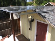
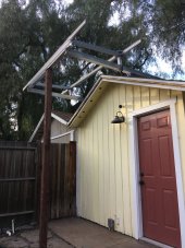
- Aluminum I-beam cantilever + 80/20 frame as a "solar awning" over my workshop entrance. Hinged for seasonal angle adjustment. South-facing. The picture was taken before one additional 80/20 "strut" plus "track" was mounted, which supports the weight when configured to a more upright angle.
- 4x 210W Newpowa 24V configured as 2S2P (purchased; not mounted yet. I'm planning to mount my panels tomorrow; weather permitting.)
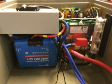
Electronics Box:
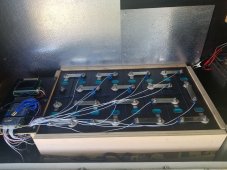
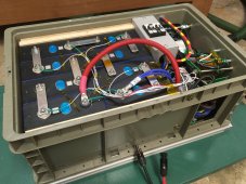
- 8s 280Ah EVE from Basen
- 8s / 24V BMS from Overkill Solar
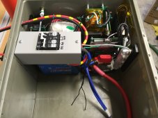
- 100V / 50A MPPT from Victron
- 1200VA Phoenix inverter from Victron (casing removed; minor modifications to the frame for mounting it; more major modifications to wire in the automatic transfer switch to the existing outlet)
- MidNite Solar 50A battery breaker, 20A PV breaker, 0.5A/63A GFP protection in a mini breaker box. Ignore the incorrect sharpie labels; that's been fixed since the picture was taken.
- Xantrex automatic transfer switch (removed from case) + RV power inlet on the side of the box (not shown)
- BlueSea MRBF dual fuse, although not actually mounted on the battery terminal for height reasons (I'm aware of class T fuses; just didn't use it since I think/hope MRBF + DC-rated breakers + BMS + fuse inside Victron inverter will be sufficient). This is mounted on an insulated standoff, which is itself mounted on two risers; see pictures.
- Battery compression fixture is TBD; it will probably be a rectangular hoola-hoop compressing from the exterior of the plastic box; probably using 80/20 aluminum
- Electronics all fit in ~13.25" x 7.5" x 7.5" (shoebox sized?). I think this may be one of the most compact builds on the internet. The box is the Quantum Storage RSO2415-9. If I were to do this again, I would definitely use that box for a 4s build but not an 8s build.
Things that didn't go so well:
- BougeRV PV cable, although it appears to have nice thick insulation, is a huge pain to deal with in a box. It's so stiff; may not even be copper, and was a huge mistake. I used it anyway for the PV since it's 10ga (30A) and I only need about 9.5A for the PV since it's such high voltage, and the breaker is 20A. But, in the future I would prioritize more flexible wire for a compact build like this
- 80/20 is great and extremely strong, but very pricey, and it's sort of a pain to assemble. Getting all the T-nuts aligned to thread the bolts into took some time. I did get all the 80/20 used on Craigslist though, so that was good, and I can see how every bit of it would be recyclable again and again for other projects, as long as the pieces are long enough.
- The box I chose doesn't have enough space for threaded rods between the two sets of 4s batteries, as well as all the electronics. So, I'm going "external" for cell compression; that hasn't been implemented yet. In a future build I would just oversize the box a lot more to make my life easier. However, I'm pleased with how little space everything took; it just required a lot of labor, drilling+tapping holes, polyimide tape, and wire ties to get there. I removed or modified the casings of a few components. In the end the heat-sinking is probably quite good as they're all mounted to a shared hunk of metal, and I used heatsink compound where appropriate. However, since it's so compact the energy density is higher. I plan to add an exhaust fan, as I mentioned above. It hasn't arrived yet.
Still to do:
- add a vent cover for air inlet + add the 24V exhaust fan + outlet. Until that arrives I'll just use this with the lid removed and perhaps a fan blowing at it. Realistically usage will be light until this thing is vetted for several weeks at light loads. The the plan is to run a ~1kW window AC over the summer off of solar power.
- mount the PV panels on the hinged 80/20 frame
- look at efficiency / calibrate the BMS (there's no shunt monitor so capacity and current are approximate, I would say); tinker with settings over bluetooth
- maybe do an IR image under load to look for high-resistance spots. I used abrasive anti-oxidant for the first time and have my doubts (ACE hardware generic of "NoAlox", I believe).
- cut a hole in the box lid for the breaker switches to stick through
- tape down or wire tie a few more cables to keep it nice and organized
- capacity testing; realistically I don't care and I'll measure this in "hours of air conditioning" before the ATS switches over to the grid
PV:
- Aluminum I-beam cantilever + 80/20 frame as a "solar awning" over my workshop entrance. Hinged for seasonal angle adjustment. South-facing. The picture was taken before one additional 80/20 "strut" plus "track" was mounted, which supports the weight when configured to a more upright angle.
- 4x 210W Newpowa 24V configured as 2S2P (purchased; not mounted yet. I'm planning to mount my panels tomorrow; weather permitting.)
Electronics Box:
- 8s 280Ah EVE from Basen
- 8s / 24V BMS from Overkill Solar
- 100V / 50A MPPT from Victron
- 1200VA Phoenix inverter from Victron (casing removed; minor modifications to the frame for mounting it; more major modifications to wire in the automatic transfer switch to the existing outlet)
- MidNite Solar 50A battery breaker, 20A PV breaker, 0.5A/63A GFP protection in a mini breaker box. Ignore the incorrect sharpie labels; that's been fixed since the picture was taken.
- Xantrex automatic transfer switch (removed from case) + RV power inlet on the side of the box (not shown)
- BlueSea MRBF dual fuse, although not actually mounted on the battery terminal for height reasons (I'm aware of class T fuses; just didn't use it since I think/hope MRBF + DC-rated breakers + BMS + fuse inside Victron inverter will be sufficient). This is mounted on an insulated standoff, which is itself mounted on two risers; see pictures.
- Battery compression fixture is TBD; it will probably be a rectangular hoola-hoop compressing from the exterior of the plastic box; probably using 80/20 aluminum
- Electronics all fit in ~13.25" x 7.5" x 7.5" (shoebox sized?). I think this may be one of the most compact builds on the internet. The box is the Quantum Storage RSO2415-9. If I were to do this again, I would definitely use that box for a 4s build but not an 8s build.
Things that didn't go so well:
- BougeRV PV cable, although it appears to have nice thick insulation, is a huge pain to deal with in a box. It's so stiff; may not even be copper, and was a huge mistake. I used it anyway for the PV since it's 10ga (30A) and I only need about 9.5A for the PV since it's such high voltage, and the breaker is 20A. But, in the future I would prioritize more flexible wire for a compact build like this
- 80/20 is great and extremely strong, but very pricey, and it's sort of a pain to assemble. Getting all the T-nuts aligned to thread the bolts into took some time. I did get all the 80/20 used on Craigslist though, so that was good, and I can see how every bit of it would be recyclable again and again for other projects, as long as the pieces are long enough.
- The box I chose doesn't have enough space for threaded rods between the two sets of 4s batteries, as well as all the electronics. So, I'm going "external" for cell compression; that hasn't been implemented yet. In a future build I would just oversize the box a lot more to make my life easier. However, I'm pleased with how little space everything took; it just required a lot of labor, drilling+tapping holes, polyimide tape, and wire ties to get there. I removed or modified the casings of a few components. In the end the heat-sinking is probably quite good as they're all mounted to a shared hunk of metal, and I used heatsink compound where appropriate. However, since it's so compact the energy density is higher. I plan to add an exhaust fan, as I mentioned above. It hasn't arrived yet.
Still to do:
- add a vent cover for air inlet + add the 24V exhaust fan + outlet. Until that arrives I'll just use this with the lid removed and perhaps a fan blowing at it. Realistically usage will be light until this thing is vetted for several weeks at light loads. The the plan is to run a ~1kW window AC over the summer off of solar power.
- mount the PV panels on the hinged 80/20 frame
- look at efficiency / calibrate the BMS (there's no shunt monitor so capacity and current are approximate, I would say); tinker with settings over bluetooth
- maybe do an IR image under load to look for high-resistance spots. I used abrasive anti-oxidant for the first time and have my doubts (ACE hardware generic of "NoAlox", I believe).
- cut a hole in the box lid for the breaker switches to stick through
- tape down or wire tie a few more cables to keep it nice and organized
- capacity testing; realistically I don't care and I'll measure this in "hours of air conditioning" before the ATS switches over to the grid
Attachments
Last edited by a moderator: