diy solar

diy solar

99.5% Efficient Inverter Design

Bob,
Try running it without the transformer, just the bare electronics, see what the idling power of that is. That will at least give you some idea of what is going on.
Yes, the inductive part of the magnetising current is theoretically lossless, but eddy current and hysteresis losses in the core are in phase and resistive. They heat up the iron directly. Better material, thinner laminations, and lower operating flux density are the way to go with that. Toroidal core with sufficient turns will give you all three benefits. Also, the permiability of grain oriented silicon steel is very high, so more inductance, and lower inductive current component.
Its a win, win, win, situation. Typical idling power for 5Kw toroidal transformer at 1 Tesla around 20 to 30 watts. Typical idling power for commercial iron stamped laminations at 1.4 Tesla maybe 100 watts plus.
I am in Melbourne Australia, we are 230v 50Hz three phase here. I have all three phases at home, which is very useful.

Nonocab,
Interesting concept. Of course if your zero load idling power is say 50 watts, and you hook up a 50 watt load to it, the input power might in theory be 100 watts in for 50 watts out, even if there were ZERO additional resistive losses.
Fifty percent is not good, and that is the problem with all inverters.
It may very well give 4.95 Kw out for 5.0Kw in (99% efficiency) at full load, but if run typically as a domestic inverter it will hardly ever see full rated power, and then only briefly.

So the general thrust for better efficiency should be more towards reducing the zero load idling power rather than trying to make it more highly efficient at extreme high power.
The big problem with off grid is at night when the load is generally light, and battery capacity is brutally expensive.
The simplest circuit will probably be the most efficient, direct single stage conversion dc to ac with rectangular waves the most efficient overall.
PWM does that, and so does a Warpverter. Anything requiring two or more stages of conversion, is likely to be less efficient overall.
 
So the general thrust for better efficiency should be more towards reducing the zero load idling power rather than trying to make it more highly efficient at extreme high power.
this is exactly the issue addressed with this resonant push pull converter, see the efficiency curve at low output
 
Certainly an interesting approach, but way beyond the average hobbyist and home constructor to get working.
Many people in Forums such as this one, expect to be able to home build a high power inverter themselves, do not even own an oscilloscope.

I get many complaints that the Warpverter is far too complex and uses far too many components, and its just four hard switched low frequency square wave bridge inverters.
It would also take several of these circuits to get the individual fully isolated supplies needed to generate a very rough stepped sinusoid.

Its still interesting though, but unfortunately way beyond what any electronics novice could hope to build and get going.
 
One further thought on all this (for what it is worth).

PWM, a Warpverter, or the switched battery bank idea discussed earlier, are all bi directional.
In other words, any of these inverters can be back fed by a grid tie inverter to charge the battery via the main inverter.
Any excess power generated by a grid tie inverter, and not used by the fluctuating domestic ac load would flow back into the battery.

There are a few things to be aware of though, the grid tie inverter must be less powerful than the main inverter (obviously) if this reverse battery charging idea is not to overload the main inverter.
The mppt on the grid tie inverter should do a splendid job, but there would be nothing to control limiting the final charge into the battery.
Some type of clever control system would need to be designed to shut down or limit the output of the grid tie inverter when the battery reached maximum allowable voltage.

Grid tie inverters are fairly fussy things about what they will synchronize to. If the main inverter is not of the pure sine wave type, but has a very distorted non sinusoidal waveform, or if the ac voltage surges or sags beyond certain limits, the grid tie inverter may spit the dummy and refuse to cooperate. Surges and sags due to things like refrigerators and airconditioners starting up are difficult to avoid.

This definitely works with a good PWM inverter, and has been demonstrated to work with a Warpverter. It may or may not work with a switched battery bank type of inverter. That has yet to be proven.
But if it does work reliably, it might solve the difficult problem of recharging a bunch of galvanically isolated battery banks without too much added complexity.

Anyone here game to give this a go ??
 
the problem with gridtie inverter is the user is unable to adapt some critical value to make a whole system working fine.
it's a closed source and for a very long time i bet on this;
bitwise if DIY isolated converter reach the diy community i think there is a lot of potential in battery management like cell balancing, converting weak AC generator to battery, a lot of proffesional charger doing real shit and think we have a nuclear powerplant at home,
supplying an chinese AC220V module with 380vdc, ect... in fact, every product the user need to make his setting to integrate a whole system

today, isolated boost converter in the range of 95% efficiency are in the open litterature.
i know i can bought everything at the same brand and it's supposed to work
 
this is exactly the issue addressed with this resonant push pull converter, see the efficiency curve at low output
I'm using the resonant push-pull to get from 48v up to near 200v to invert. I've got it simulated in LT Spice and looks reasonable. It's open source so simulations are up for grabs if anyone wants.
 
I'm using the resonant push-pull to get from 48v up to near 200v to invert. I've got it simulated in LT Spice and looks reasonable. It's open source so simulations are up for grabs if anyone wants.
Nice job, what kind of efficiency we can have at low power output like 5% of rated power?
 
There is a study, on relative simplicity, a clever way to make isolated converter and stay with "low" switching frequency at 20khz
 

Attachments

  • High efficiency isolated DC⁄DC boost converter with planar magnetics.pdf
    661.4 KB · Views: 24
What a perfectly odd topology......
Its certainly not a half bridge circuit as the author suggests.
More like a kind of weird push pull flyback topology driving a voltage doubler through a 2:1 step up transformer.
Its a rather sneaky way to generate a high voltage though.

As he states, the mode of operation totally changes below 50% duty cycle, it becomes discontinuous, which would make the design of a stable voltage feedback network rather challenging. At very low loads it MUST operate at lower duty cycles than 50%.

What modern topology isn't weird :)
the ratio 2:1 can be changed.
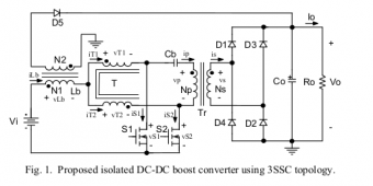
Maybe there is a way to handle near 50% duty cycle and evacuate energy in inductor like that D5 an N2 winding on that similar design:
but why setting duty cycle under 50% if the tranformer ratio is ok for a range of voltage at the output?
 

Attachments

  • 3ssc.png
    3ssc.png
    26.4 KB · Views: 4
Cb is a very good idea, it keeps any dc out of the transformer. The choke should obviously be bifilar wound. The circuit is great and very innovative, but its going to be a cranky beast where very sudden step load changes are required through the 50% duty cycle point where it changes mode of operation from continuous to discontinuous current through the choke. And the flyback right half plane zero demon is the stuff of nightmares.

It would probably be o/k charging a high voltage battery, or something similar, where sudden drastic line and load changes were not involved.

As the front end for a high voltage transformerless PWM inverter, I cannot get very excited about the prospect of getting it to work very well.

If I was not now retired, and was tasked with this, I would build a good old fashioned boring meat and potatoes push pull forward inverter with a full wave rectifier and choke input filter at the magic 20Khz. At higher input voltages a bridge converter along similar lines. Very basic low tech that works.
 
Last edited:
I like this circuit because of low ripple current at input, well for solar with small capacitors, well for battery too.
And about duty cycle i think regulation don't need to go under 0.5 because voltage gain ratio needed to charge something at the output of this circuit, drop very fast near 0.5 duty cycle, but maybe it's an illusion. Real working electronic is revealed at the real life testing and i agree nightmares can happen at very low load!
 
It certainly has that going for it, but a big electrolytic at the input will solve the high ripple current problem with a solar PV panel.

Any constant current topology has issues with sudden step load changes. The more energy stored in the choke, the worse the transient response in both directions.
 
Yes i understand what you said about the energy stored in the choke.
I think it's possible to stay in continous current mode, but the frequency of converter have to increased near 0.5 duty cycle it's will reduce the current in the choke and main transformer will stop to transfert energy to secondary. Only the winding N2 unloading the choke will transfert energy to output but as the current in this choke will be negligeable, the energy transfert will be very very low; If not enough maybe add an third winding N3 to unload the choke at the input of converter instead at the output.

Or a lot brain idiot; just keep the normal duty cycle 0.75 and keep going in flyback mode with the choke to regulate the very low idle power, i just have to drive 2 mosfet gate together.
Ah ah I have to test this :coffee:
 
Last edited:
No you cannot stay in continuous mode if there is zero load on the output.
No way around that.
If there is zero output load, there will be nowhere for any current to go.
Its all jolly good fun, and the last flyback solar controller I built was discontinuous right up to the full flat out 1Kw.

The reason I did it that way was the solar input voltage could be either more than, or less than, the required regulated dc output.
Very easy to control and regulate if it stayed discontinuous right up to full power.

I am sure that circuit will work super well with a fixed load. But closing a voltage feedback loop around it is going to be probematic.
 
Nice job, what kind of efficiency we can have at low power output like 5% of rated power?
I expect similar numbers to the paper presented using silicon switches at 100-200 kHz with resonant secondary. 5% would be 250W out. The difference there in lost power between 90% and 96% is only 15w anyway so not too too concerned there. I am heating 2" concrete slab on second floor with extra solar I have so I have a little bit of headroom. The resonance will allow for soft switching at both turn-on and turn-off of the primary switches. Major share of losses will be conduction losses on primary side. With output at low currents that you suggest the conduction losses should be very low as square law and heatsink will be very cool too. I will use not be using sync rectifiers on the output tho so some inefficiency at the higher loads. SiC diodes on the secondary side.
 
I intend to run DC-DC converter portion open loop. I'm seeing 170v-200v from 200W to 5kW load. I think I can run a slow feedforward loop on the inverter side and do fine.
 
I intend to run DC-DC converter portion open loop. I'm seeing 170v-200v from 200W to 5kW load. I think I can run a slow feedforward loop on the inverter side and do fine.
what physicals inputs did you use to modelize your feedforward loop?
 
Its really simple. No model requred its linear correction.
If the input voltage falls by 13.4% the feedforward jacks up the ac output voltage by 13.4% so the output does not change.

Just measure the incoming dc voltage with an analog to digital converter and use that voltage reading to adjust the ac output amplitude directly.

Unlike ac, you can take an instantaneous snapshot of a dc voltage at any time.
Ac requires rectification and some kind of cycle to cycle averaging which is always...... S L O W.
If you make your amplitude changes right at the zero crossing, there will be no waveform discontinuity, massive instantaneous amplitude corrections are possible, and you can correct for input voltage changes every half cycle if you want to.
Its super fast, very accurate, and zero chance of any loop instability because there is no loop and no voltage feedback is required.

In the case of the Warpverter, I have 256 different 1K lookup tables that adjust the switching pattern to suit the dc input voltages over a 2:1 input voltage range. Works extremely well. No reason why it cannot also be done using PWM.
Line changes (dc input voltage) are 100% corrected.

AC output voltage will always sag a bit under load, due to finite resistance in the power stage, whatever that may consist of.
Even direct grid power voltage will sag a bit under load, nothing has zero source impedance.
Just using voltage feedforward correction is perfectly acceptable for an iverter.

If you really want to get serious, its possible to also measure the dc input current with a Hall sensor and use that to add further voltage correction in the same way the input voltage is corrected.
I have not bothered to do that in my own personal inverter, but another Warpverter builder has done it (Klaus on the Back Shed Forum) and he can tweak that for perfect output voltge regulation under varying load.
In fact it can be overcompensated to RAISE the output voltage as the load increases, but there is no practical reason to do that.

Interstingly, it also works in reverse when back feeding power from a grid tie inverter, the current compensation prevents the ac voltage from rising as ac power is fed back INTO the inverter.
Its all really fascinating stuff.

I would not bother with voltage feedback in any inverter design these days, its always going to be slow, and prone to instability even if your PID loop is tuned to perfection.
Feedforward offers much faster correction and minimal light flicker when a very heavy load cuts in or out because correction is so vey fast and complete.
 
Back
Top