diy solar

diy solar

A little math help please.

Terrapin

New Member
Joined
Jan 4, 2021
Messages
315
Location
New England, USA
I did find a few posts on how to calculate the amperage draw off a 12 bank to run inverted 110-120v loads but I am math challenged, dyscalculia to be honest. It makes some of this just very difficult. And when it comes to fuses, well pride be damned. I am just going to ask for the help.

Can someone dial me in on running an inverter rated at 2200W/4400peak. Shutoff is rated at 2200 to 2500w output. Documentation does not mention efficiency so a safe conservative guess is welcome. (It is a Giandel 2200W Pure sine if that matters) I am simply looking to know what the max amp draw out of the battery bank will be to see what wires/Anderson connectors/breakers will meet the needs of this inverter.

I am still working on the logistics of protecting the battery from being over discharged. For now it will be monitored closely.

And yes, I understand this is really pushing 12V and 24 should be the choice, but the entire trailer and onboard converter is 12v based and will need to stay that way. Max use of the system will be fleeting perhaps a max 10 min runtime of a microwave and pretty rare, but I want it available on demand to make the Mrs. happy. All other 12V loads will have a separate battery with breakers and wiring based on the BMS abilities.
 
Easy math is take the watts and divide by the battery voltage.
That will get you approximately. Inverter efficiency will be add 20% to the result.
So, 4000W peak really shouldn’t be the consideration with a giandel HF inverter.
2000W /12V is 167A
Plus 20% for losses is 200A
 
Math free way to get the fuse size? Looks like Amy (aka @SolarQueen) has you covered:
Easy math is take the watts and divide by the battery voltage.
That will get you approximately. Inverter efficiency will be add 20% to the result.
So, 4000W peak really shouldn’t be the consideration with a giandel HF inverter.
2000W /12V is 167A
Plus 20% for losses is 200A
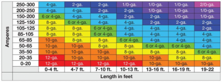
Edit: Whoa! hold on. the linked chart from Amy says 4/0 gauge :oops:for under ten feet run with a 250A breaker. But that calculated 200A shows 4 or 2 gauges between 7 to 10 feet. That's a huge difference?1?! I am lost...

1617283140179.png
 
...the linked chart from Amy says 4/0 gauge :oops:for under ten feet run with a 250A breaker. But that calculated 200A shows 4 or 2 gauges between 7 to 10 feet. That's a huge difference?1?! I am lost...

What @Supervstech says in his calculation is:
...the 4000W peak really shouldn’t be the consideration with a giandel HF inverter....

Hate to speak for Amy (@SolarQueen) or @Supervstech , but I'm pretty sure Amy's chart is for quality inverters that can sustain surge rating for a few seconds. If the surge is 4kW, than 4000/12 = 334 amps and matches the table. With Amy's setup, you'll never have to worry about overheating or voltage drop. It is a safe and conservative choice.
 
Just to put it out there, the math I use is 2200W / 12V x 1.25 = 229A, round up to 250A fuse (or breaker).
 
The NEC says the ampacity (current capacity) of AWG 4/0 is 260A, and for AWG 4 it is only 130A. Now, the NEC is really conservative, and all about safety. The resistance of #4/0 is 0.05 ohms per thousand feet, and for #4 it is 0.25 ohms per thousand feet. So if you have 200A and a 10' run, the drop in a #4/0 cable will be 200 x 0.05 / 1000 * 10 = 0.1 volt. For #2 wire it would be 200 * 0.25 / 1000 * 10 = 0.5 volts. If you are in a 12V system, a half volt drop can make a difference. If you can afford it, go with some #4/0 welding wire and feel good about it.
 
Edit: Whoa! hold on. the linked chart from Amy says 4/0 gauge :oops:for under ten feet run with a 250A breaker. But that calculated 200A shows 4 or 2 gauges between 7 to 10 feet. That's a huge difference?1?! I am lost...

View attachment 43351

I used the bluesea online calculator myself, I will use a 3000va victron multiplus at 24v. That should draw 125 amps at full capacity, so I used 140 amps (inverter efficiency) which happens to be the .5C discharge rate for Eve cells. Bluesea recommended 4 gauge wiring and 200 amp breaker and fuse, so I am using 2 gauge wire and Busman 200 amp breaker (mainly as a switch) and a 200A class T fuse. The 250A Daly bms that I am using also just happens to use 2 gauge wires. It made little sense to use bigger wires when the bms doesn't. Remember that fuses and circuit breakers can affect your calculations, since both produce heat. Calculations are based on a 30 degrees Celsius rise in the wire temperature, and I would like a lot less.
 
I think that you should start from the highest LOAD which your DW will be "allowed" to run through the Inverter. The Inverter claims to be able to run 2200 W continuous, on the spec sheet, but it might not really be capable of doing that. (As with pre-built LFP batteries, many such products are over-advertised.) From there, I would work backwards from the load - The AC wiring must be adequate (bigger than the corresponding wire size), and the AC Circuit Breaker should be the hard limit.

For an inverter "advertised" at 2200 Watts (slightly more than 18A) I would be inclined to choose a 15A breaker, allowing no more than 1800 watts continuous. That's running the Inverter at more than 80% of capacity, and I would NOT want to "stress its guts" by running higher than that for any appreciable length of time. (Resetting the Breaker is cheap. Replacing the Inverter? Not cheap.)

From there, I would work backwards to size the DC side as follows: Assume around 80% efficiency within the Inverter while running at 80% of capacity - that's back up 2200W consumed in the input side. Depending on the SOC and current capability of your bank it might be anywhere from 12.0V up to almost 12.8V while pushing all of this current.

Our next factor (and I think that SolarQueen presented a fine semi-SWAG for this, not having the DC supply wire length supplied by you), is to account for additional Voltage Drop incurred by wiring loss on the DC wires from the battery bank. You need to get that from an online calculator, using your EXACT distance between the Battery Bank output bus connectors and the Inverter DC terminals. I wouldn't want to have the Inverter pulling higher current on the DC side, making up for "too much" Voltage drop. 2/0 wire would be VERY questionable, except for the case of extremely short distances (in which the total Voltage Drop will be small, and much of the "wiring-loss" heat would be dissipated to the Inverter Terminal and the Inverter's cooling fan. If you are extremely short (the distance on my own Inverter connection is about 18 inches), then "Chassis Wiring" capacity rules apply - and the NEC Ampacity of 2/0 wiring is adeqaute, at 283 Amps.
- - -
If you limit DW's usage on the AC side by using a 15A Circuit Breaker, and if your battery bus can put out around 190A while still maintaining
a Voltage of at 12.5 or higher, then your maximum continuous load CAN be met by a 2/0 wire at two feet or less, with a breaker size of 200A (more likely to open during "spikes" in demand from the Inverter) or 250A (less likely to open, but getting awfully close to the maximum Ampacity of the cable). Otherwise, you're back up to SolarQueen's wise and larger general wire size requirement: 4/0 wire and a 250A breaker on the DC side.
 
Last edited:
A general point:
A lot of the confusion on this particular topic comes from a few places:
  1. Properly sizing wire depends on two factors (A) Voltage drop (B) Ampacity, many of the charts you find online only address the first factor but don't always explictly state that (which is irresponsible in my opinion
  2. There is no static ampacity for a given wire gauge, insulation temperature and other factors (like ambient temperature) matter. So the number a calculator outputs depends on the assumptions and variables of the input.
Personally I like the Blue Sea Circuit Wizard and the Bay Marine Supply Calculator. I believe both account for both ampacity and voltage drop, and consider some of the variables that other calculators ignore.

Or if you prefer to go right to the horses mouth, here are the charts (ampacity) from the NEC (for <30* ambient) and ABYC (for 30* and 50* ambient):
ABYC
NEC
You would still need to calculate voltage drop separately by hand or using one of the calculators above (or any other) but this is more straightforward.

In terms of the math to find out max amperage of your inverter, I'm far from an expert but this is how I do it:

[Inverter Watts] / [Inverter efficiency] / [Inverter Low Voltage Disconnect] = [Max Inverter Amps]

So if you want to be conservative maybe:
2200W / 0.8 efficiency / Giandels low voltage disconnect (11V?) =
250A

Efficiency may be higher or lower, the low voltage disconnect is just a guess, not sure what the actual value is, so this may be higher or lower too, adapt these numbers to what fits your system.
I will add to this that you should also have some fuse headroom so as to avoid nuisance trips.
250 amps / .8 fuse headroom = 312.5 fuse amps
Then round up to the next fuse size.
Then you need a wire that can handle the ampacity of the chosen fuse.
 
This horse may already be dead, but let me take one more swing....

Everyone learns early that going with a higher DC voltage in your system reduces the cost of the wire, but not everyone realizes that it is a COMPOUNDING effect.

First, to achieve a given number of DC watts requires less current with a higher voltage than it does for a lower voltage. This part is easy. To get 1200W at 12V requires 1200 / 12 = 100A, but 1200W at 24V requires only 1200 / 24 = 50A. This lets you use smaller wire.

But the second point is sometimes not noticed: The loss your system has due to current in the wires has a lesser impact. Say you have 100A going through 10 ft of #2 wire that has a resistance of 0.25 ohms per thousand feet (the example I gave earlier). The loss across those 10 ft is 200 * 0.25 / 1000 * 10 = 0.5V. This 0.5V loss is independent of what the voltage is. However, 0.5V is a 4% loss in a 12V system (0.5 is 4% of 12V), but only 2% in a 24V system (.5V is 2% of 24).

So, using a higher voltage lets you use less current for a given wattage, AND that current causes less of a loss across the wire. Winner!
 
  • Like
Reactions: Dzl
I will add 1 more thing.
Even though 2/0 awg will handle ~330 amps without melting the insulation off wire rated for 105C, most people probably don't want their wires getting hotter than boiling water.
 
Back
Top