diy solar

diy solar

About to pull the trigger on a system, but have a few questions 400 Watt solar Travel Trailer

tetonmtnbiker

New Member
Joined
Jun 9, 2020
Messages
27
Hello All,

I’ve been lurking for a while and am read to take the leap. I have a new imagine xls travel trailer with “solar prep” (10 gauge wire running from the roof).

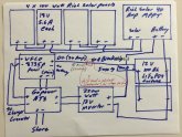
i attached my wiring diagram (plagiarized from Will’s classic system) and have a couple of questions if someone would be willing to take a look.

1) is the 10 gauge wire in the solar prep sufficient for the current from the solar array as configured?

2) is the 300amp breaker the right size? (I used the chart from One of Will’s links, but I want to make sure I’m right here)

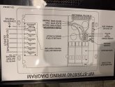
and, here is where it gets complicated... I want to use (if possible) the onboard power center in the new trailer. I am planning on installing a Go Power ATS that has a separate power out for the charger / controller In my power center. I am planning on running the main power out of the ATS into the main in the WFCO panel (wiring diagram also attached), but attaching the ATS’s Charger/converter line into the the wires labeled “from converter” in the WFCO. i believe that when I am on solar/battery power that line will not be activated and I won’t have the “batteries charging themselves loop”. I plan on attaching the WFCO posts labeled “white to battery negative” and “to converter positive” back to the battery bank. Also, I am planning on using the existing power wires That run to WFCO for both shore (that will now be coming out of the ATS for AC) and the DC side (currently from the cheap battery that came with the trailer (8 AWG)). finally, i think I may need something to interrupt the charge function of the WFCO when on shore power because I fear that unit cannot charge my lithium batteries safely (and solar should do it just fine when I’m on shoe anyway). As such I am thinking of adding a contactor to interrupt the line to the battery when it senses power coming out of the “to charger / converter” out of the ATS. That way the line is “broken“ to the battery when on shore, but the converter still is operational. But I have 4 questions.

1) will this plan even work (I’m afraid I may be reading the WFCO diagram incorrectly and have the wiring wrong back to the battery)

2) will the 8 AWG wire currently running from the the battery that came with the trailer be large enough t run to the DC side of the WFCO (total ~20 feet (that is shorter than current factory setup))?

3) do I need the contactor (or some other way) to stop the shore power from trying to charge the battery bank

4) am I missing anything else

BTW - I’ve really enjoyed geeking out on Wills videos and this forum. And the battery “bank” will actually be a fortune 4s2p single Battery with a BMS. Thanks in advance, you guys rock!

jeff
 

Attachments

  • image.jpg
    image.jpg
    86.5 KB · Views: 32
  • 8F10A268-2714-4B64-90D5-6377BFFB6A7D.jpeg
    8F10A268-2714-4B64-90D5-6377BFFB6A7D.jpeg
    97.7 KB · Views: 31
What inverter are you planning on using? Is it a standalone inverter or an inverter/charger?
 
it is a standalone inverter.
Pure Sine Wave Power Inverter 2200Watt DC 12volt to AC 120volt with Dual AC Outlets and 2.4A USB Port & LED Display Remote Controller for RV Trucks Boats and Emergency
by Giandel

I have answered a few of my question though. My wire gauge size I'm OK with.

I now plan on using the ATS as I mention above, but having a manual battery shutoff between the power center back to the battery to disable charging when on shore power. The tech support guy at WFCO said theirs is a smart charger that will not charge above 90%, but I don't like the idea of the WFCO charger and the solar charger working at the same time on my expensive lithium batteries.
 
1593549132260.png
It looks like this is your transfer switch. It's nice that it has that separate switched feed for the charger feed. I agree that you don't need to worry about 2 chargers feeding your battery at the same time. If you trust the WFCO charger to ever charge your batteries, then there is no problem having it charge while the solar is also charging.

Here is a link where I posted the before and after schematic that I installed on a prior trailer that I installed solar on. In that setup I had a Magnum inferter/charger. So I disconnected the converter/charger in my power station as that function was handled by the Magnum. The transfer switch was included in the Magnum as well. But you have the same components: Inverter, Charger/Converter, and Transfer switch so it looks like it will work fine as long as you can connect the transfer switch AC power feed to the WFCO AC breaker panel and the Charger feed to the WFCO charger wiring.

Link
 
Depends on the capacity of your battery bank and the max charge and optimal charge rates.
If both charge sources are within the max charge rate then go for it.
If both charge sources are going to cause stress to your battteries then you need to manage that.
 
Thanks for the feedback!

That is my ATS bpal. Thanks for the link to your system. I'll check that out when I'm supposed to be working later today.

Smooth Joey, I have 8 fortune lithium 3v 100 Ah cells (or I will anyway) configured 4s2p so 12V 200Ah. I will check charge rates etc on those and verify the sources are both compatible. I am going to add a breaker between the Shore charger and the battery either way to give me the option of shutting it off.

Placing the order today!
 
One more question on fuses and wire size. I am planning on using 6 gauge wire from the rich solar 40 MPPT. 1/0 gauge wire main from the battery (Fortune 12v 200Ah lithium bank). All runs less than a foot between inverter / battery / MPPT. I originally was going to use a 300A main fuse, but I think I need to drop to a 250A. And for my breaker to the MPPT I'm planning on using a 50A breaker. Also, I am planning on using 15A inline fuses from the panels on the roof (2 total before the series trunks are joined). Does this look right to you guys?

Thanks,
Jeff
 
One more question on fuses and wire size. I am planning on using 6 gauge wire from the rich solar 40 MPPT. 1/0 gauge wire main from the battery (Fortune 12v 200Ah lithium bank). All runs less than a foot between inverter / battery / MPPT. I originally was going to use a 300A main fuse, but I think I need to drop to a 250A. And for my breaker to the MPPT I'm planning on using a 50A breaker. Also, I am planning on using 15A inline fuses from the panels on the roof (2 total before the series trunks are joined). Does this look right to you guys?

The biggest fuse you can use with 1/0 awg 105 Celcius wire is 285 amps.
If you post a diagram I will audit the whole thing.
Probably others will too.
Its a really good way to get the plan to gel and get many eyes upon it.
@tictag
 
Last edited:
1) is the 10 gauge wire in the solar prep sufficient for the current from the solar array as configured?
Your panels appear to be configured as 2S2P so PV current to your SCC will be 2 x Panel Isc. I'm guessing "5.6A" is Imp, so Isc will be around 6.7A, so 13.4A. I'm guessing 20' PV cable run so in order to stay below a 3% voltage drop you'd need a minimum of 12AWG (2.85%), so 10AWG (1.49%) will be ideal.
2) is the 300amp breaker the right size?
No. Please read @FilterGuy's excellent post of fusing and fuse selection here.
You need to fuse each circuit connected to your battery separately. If you were to use a single 300A fuse ALL you cable would need to be a minimum of 4/0AWG. That's a very expensive design choice.
1) will this plan even work (I’m afraid I may be reading the WFCO diagram incorrectly and have the wiring wrong back to the battery)
I don't know enough about this WFCO to comment authoritatively, for example, what does it mean "From Converter"? Is it referring to an Inverter? But I would urge caution, if it does mean 'Inverter' then you must not do what you're planning to do. Your GoPower ATS does not switch the shore power input from the charger, it just acts as a convenient terminal block, so in the scenario where you are switched to Inverter supply the moment you connected shore power you would be directly, albeit momentarily, connecting your inverter to the grid.
2) will the 8 AWG wire currently running from the the battery that came with the trailer be large enough t run to the DC side of the WFCO (total ~20 feet (that is shorter than current factory setup))?
I don't know what DC loads you have, also on your diagram you have written "10AWG (existing)", but anyway your diagram indicates 30A so an 8AWG cable pushing 30A along a 20' cable run would drop 6.2% of the supply voltage, definitely sub-optimal. You would need at least 4AWG cable to get below the generally preferred 3% voltage-drop.
3) do I need the contactor (or some other way) to stop the shore power from trying to charge the battery bank
No, just power your charger directly from shore power (and only shore power). If shore power is not available, the charger doesn't charge.
4) am I missing anything else

Other considerations:
  1. Consider adding a DC isolator to both PV and Battery circuits, it's best not to have to work on a live system if you can help it.
  2. Your SCC supports up to 100V on the PV side, consider configuring your PV array as 4S1P giving you an array Voc = circa 86.4V, reducing your PV current down to circa 6.7A meaning that you can use reduce your PV cable size down to around 18AWG and still maintain a below 3% voltage drop (over estimated 20'), saving you money.
  3. Consider using busbars instead of directly connecting device to device. Easier long term, trust me.
  4. Connect any battery charging cables to opposite ends of your battery bank - see here for further information.
  5. So long as you RV's battery charger is current limited (which I suspect it will be) then it will be fine charging your LiFePO4 battery. Make sure, however, that Equalisation mode, if it has one, is disabled. If this is not possible, replace the charger because all it will do is trip your BMS.
Good luck with your new project.
 
No, just power your charger directly from shore power (and only shore power). If shore power is not available, the charger doesn't charge.
Ahhh, just realised, you want to stop shore power charging in order to use your PV array. Sorry, misunderstood.

Your SCC has a 'load out' feature, you could use this to power a simple relay that switches the supply to your charger. Better to cut the supply rather than the output because the charger itself will have a no-load power drain.
 
Thanks so much tictac, smooth joey, bpal and ianganderton.

I am updating my wiring diagram to reflect all of the suggestions and comments. Ill re-post this weekend as stuff starts showing up.

I really appreciate all of the time you have taken to help me!
 
Here is the updated plan. I have some comments at the bottom right. I am most concerned about fuse, breaker and wire size. Thanks All.
 

Attachments

  • solar diagram.pdf
    33.2 KB · Views: 21
everything is on the way. I have updated the diagram to reflect all of the feedback (the changes are highlighted in yellow in the diagram). I do have a question on whether I should put a breaker between the main fuse and the inverter. I have attached the diagram to show where I am uncertain if I need another breaker. Thanks!
Jeff
 

Attachments

  • solar diagram.pdf
    33.2 KB · Views: 27
2200 ac watts / .85 conversion efficiency / 12 volts = 215.68627451 dc amps
215.68627451 dc amps * 1.25 fuse facotor = 269.607843137 fuse amps.
Thats just to cover the inverter.
I see you have speced 2/0 wire which is good.
 
Back
Top