diy solar

diy solar

Absorption Time for Eve lf280k

bigbrovar

New Member
Joined
Nov 4, 2021
Messages
17
Location
Abuja, Nigeria
Hi guys, I am completely new to Lifepo4 cells having just set up my bank less than 2 weeks ago. I did alots of research and had to unlearn everything from using Lead Acid batteries for over 6 years.

I have Eve LF280K 16s
BMS is JBD 7S-20S 200A

One area I am a bit unclear about is around absorption of this cells. A lot of the literature I have read says Lifepo4 does not require long absorption, in fact it is stated that once the set pack voltage is reached and tail current drops to C0.05 charging should stop.

I use a Victron Smart MPPT charge controller. The charge controller is no way of determining the battery charge current (The actual current going into charging the battery as against powering the house) so there is no way to base charging on tail current.

Victron has a LifeP04 profile which it sets to 2 hours of absorption. My concern is most of the literature seem to suggest 2 hours is too long for absorption and should in fact be not more than 30 minutes. I am new at all this and I am a bit confused. I would very much not like to damage any of the cell in the pack so I come here to seek counsel on what the proper cause of action to take is.

My current charge profile
Absorption set to 56.8v
The goal is to have each cell charged up to 3.55v
Absorption time is set to 2 hours before switching to float which is set to 3.35v per cell or 53.6v for the bank.

I live completely off the grid and have a 5kw solar array for charging the system. Charge rate is usually below C.3 but has the potential to be as high as C.4.
 
My experience is that as I lower the boost volts per cell setting, I need to increase the time that the boost voltage level is held. There is a point on the charge curve where the battery is still taking some charge (not fully charge) and the voltage has not started the quick rise toward 3.65v per cell. In this region if I stop holding boost level prematurely, I may not be fully charged. I am okay with that but still, it takes some time at these lower voltages to get your charge state up there.
 
There are two different requirements when talking about absorb time. One is actual cell charging and the other is time required to allow enough BMS cell balancing for the series array battery pack.

The JBD 7S-20S 200A BMS has very low balancing dump current of less than 30 mA so it will likely be the dominate reason for amount of absorb time required. With less balancing dump current it takes longer for cells to be balanced. BMS only enables balancing above 3.4v of cell voltage so complete balancing only occurs during absorb time. Therefore, with lower balancing dump current, you need longer absorb time to balance cells.

For charging of cell, the amount of charging current and level of absorb voltage determines required absorb time to fully charge cell. Low charge current requires very little absorb time. Charge current above 0.1 C(A) requires longer absorb time to fully charge cell.

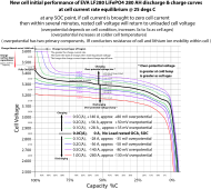
The more charge current, the greater the cell over-potential voltage rise there is during charging. Over-potential voltage is overhead required by cell to move lithium-ions through the cell to support the demanded cell current. As cell reaches full charge there is less free lithium-ions and less 'parking spots' left in the negative graphite anode for lithium-ions storage. This increases the overpotential voltage overhead required to meet the demanded cell current. This is the cause of cell voltage rapidly rising above about 3.45v during charging as it is getting close to full state of charge.

Attached chart shows the amount of overpotential voltage overhead required for charging and discharging for different demanded cell current for a relatively new cell. As a cell ages, its internal impedance rises, and greater overpotential voltage overhead is required for a given cell current. Overpotential voltage has a time delay with an exponential taper that requires about 60-180 seconds to reach equilibrium voltage after a demanded cell current change is made. The graph is cell voltage after cell reaches equilibrium for the stated amount of cell current.

In the graph attached, if you stop the charging at any point and allow the cell to reach equilibrium no-load, rested voltage, the cell voltage will drop down to the zero current graph line (black line). You can use the zero current equilibrium graph line to estimate state of charge at point charge current was terminated.

One other effect to be aware of is when a cell is fully charged, the over-potential voltage will decrease as charge current tapers down. The fixed charger absorb voltage and the decreasing required cell over-potential causes a capacitor like charge storage voltage to develop in the cell layers, dominantly the graphite negative anode. So, if you fully charge a cell to 3.6v where cell current tapers off to low level there will be a capacitance voltage charge that artificially shows a greater cell open circuit terminal voltage.

At full charge on LFP cell, an open circuit, rested, terminal voltage greater than 3.45v is a fully charged cell. The surface capacitance charge voltage will cause the voltage to be greater when first taken off absorb voltage charger. This surface capacitance charge voltage rise only amounts to the equivalent of about 0.01% C of cell capacity and can be quickly bled off with a 1 amp load in 60-90 seconds after which the open circuit rested cell voltage will be about 3.45v.

If you do not manually bleed off the surface charge it will slowly dissipate on its own but may take a day or two to completely dissipate to cell full charge OCV of 3.45v. If after a few hours from full absorb charge you see your cells have voltage variance between 3.45v and 3.60v it does not mean they are not balanced. It just means they are dissipating the surface charge capacitance voltage at slightly different rates. This variance in rate of discharging surface capacitance has nothing to do with cell state of charge or cell AH capacity.

LF280 AH battery dischg 0.1C-1.0C.png
 
Last edited:
@RCinFLA - If I read your explanation and chart correctly, you said that the extra absorb time is needed in order to allow the cells to catch up to the charging voltage, and particularly if the charge voltage is clamped at 3.45V. The charge current will then reduce as state of charge increases along the yellow line that I added to your graph (at 3.44V):


LF280 AH battery chg 0.1C-1.0C.png
 
@RCinFLA - If I read your explanation and chart correctly, you said that the extra absorb time is needed in order to allow the cells to catch up to the charging voltage, and particularly if the charge voltage is clamped at 3.45V. The charge current will then reduce as state of charge increases along the yellow line that I added to your graph (at 3.44V):
Roughly, that is correct. Keep in mind the overpotential voltage bump during charging (and slump during discharging) is dependent on cell condition.

In the graph, with your yellow line, if you terminate charging current early, the cell no-load voltage after some resting time will drop to thick black line.

The amount of resting time to drop to black line depends on how close you got to full charge. If you terminate charge current before it starts the final upward rise it will take 3-5 minutes to reach equilibrium. If you take it all the way to full charge it can take several days to finally reach 3.45v equilibrium voltage. Near full charge there is a different process happening that exchanges overpotential voltage for surface capacitance charge. This can be bled off quickly with a small (0.02% C) discharge which is about 1 amp for less than 60 seconds on a 280 AH cell.

Older cells will require more charging overpotential voltage, above no-load rested voltage, to push the same amount of current through the cell. If the cell requires greater overpotential voltage because of its age, for a given cell current, there will be more terminal voltage bump during charging and terminal voltage slump during discharging. The older cell will have a longer current taper-off period during constant absorb voltage charge.

The main point to understand is the greater the charging current, the longer the current taper-off time period during the top end, constant absorb voltage.
 
Last edited:
Sorry to revive a dead thread, though I thought I'd ask the question here as there seems to be a great wealth of knowledge among those who've commented so far.
Like the OP, I've been looking to find the best long term voltage for bulk charging and absorption for my LF280K cells.

I'm currently using some fairly conservative settings:
Bulk charging voltage: 55v (or 3.4375v per cell)
Absorption voltage: 54.5v (or 3.40625v per cell)
Absorption time: 2 hours.

I'm somewhat constrained around the absorption voltage and cut off settings due to the strangeness of the charging algorithm used by the Growatt all-in-ones.

My question: Does holding the cells at 3.40625v for 2 hours after bulk charging pose much risk? This setting provides plenty of time for balancing and works very well with the Growatt algorithm, I'm just concerned about long term effects like plating or placing undue stress on the cells. For most of the time the cells are at this voltage, the BMS measures little to no current going into them from the charger.

After the 2 hour absorption completes, charging is cut and the batteries settle to their natural resting voltage (about 3.318v) and start to drain at sunset and overnight. The whole charging cycle takes about 6 hours on a normal day.
 
My question: Does holding the cells at 3.40625v for 2 hours after bulk charging pose much risk? This setting provides plenty of time for balancing and works very well with the Growatt algorithm, I'm just concerned about long term effects like plating or placing undue stress on the cells. For most of the time the cells are at this voltage, the BMS measures little to no current going into them from the charger.
No risk to cell but you are likely not going to get much balancing.

There is tolerance to the 3.4v balance trigger voltage. Should do at least 3.45v, preferred 3.5v.

The amount of time spent at absorb to fully charge cell depends on bulk charging current rate. The greater the bulk charge current rate the longer it takes in absorb voltage range for the current to taper down indicating full charge.

Greater cell current requires greater overpotential voltage on cell to drive the required lithium-ion migration rate required to support the demanded cell current.
 
Greater cell current requires greater overpotential voltage on cell to drive the required lithium-ion migration rate required to support the demanded cell current.
And just for completeness, this is due to the fact that V = I * R. In order to have current, you must have voltage. In the case of charging a battery, the voltage/current relationship is controlled by the internal resistance of the battery (and external resistance as well, such as terminals and cabling). The internal resistance is produced primarily by the chemical reactions going on inside each cell.

The internal resistance is why one must provide a charge voltage that is higher than the voltage in the battery's chemical voltage in order to get current to flow into the battery, and why the battery measures lower than the chemical voltage when discharging the battery. That is the whole point of the chart shown above, with charge curves above the chemical voltage, and discharge curves below it.

The higher the charge voltage, the more critical it is to terminate the charge at a specified current in order to keep from overcharging the battery. Charge voltage of ~3.375v per cell is always safe because it cannot cause overcharging, but full charge will take longer due to lower current. As everybody including @RCinFLA has stated, a BMS presumes you want top balancing, which is only productive as the cells reach full charge. The BMS needs current flowing in order to do the balancing, so you must provide extra voltage to allow it to happen. With reasonably well matched cells, it is probably not necessary to balance every day or even every week.
 
Thank you both for the detailed responses. I forgot to add that I have a JK BMS with active balancer, it seems happy to push and pull current from the cells even with minimal or no charging current, just as long as the cell(s) are above the 3.4v threshold.

So 3.40625v absorption for a couple hours each day is not a problem, but I should actually consider higher to ensure good top balancing?
 
Back
Top