diy solar

diy solar

AC design on 48V all-in-one system

Mudd216

New Member
Joined
Jul 12, 2022
Messages
20
I started with Will's complete DIY 48V offgrid Solar Power System design and incorporated AC. At this point I was hoping folks could comment on the AC design to ensure I am on the right track. Next I would like to design for more flexibility and I am hoping folks could help point me in the right direction.

14KW solar, 30kWh EG4 battery kit, 4 6500EX-48
I intend to leverage solar/battery as much as possible and augment with grid/generator as needed. I have a back up propane generator with an ATS today and I want to leverage as much existing wiring as possible.
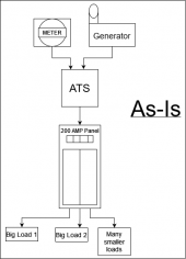
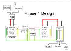
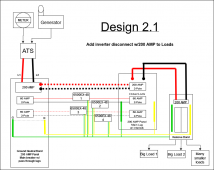
solar AC-As-is AC.drawio(1).pngsolar AC-Add Solar.drawio(1).png

I would like to add a means to easily feed the loads panel from grid for maintenance or other situation . I am thinking maybe adding a 200 AMP breaker in the first panel and running it to a 200AMP breaker in the second panel and incorporating some sort of Generator Interlock Kit such that the second panel could be energized from either 200 AMP grid or 120AMP inverters but never both. I am not sure I can find panels/breakers/interlock kit to accomplish this. Maybe the right approach would be to incorporate a manual transfer switch in front of the loads panel and feeding the switch from the first panel and second panel (inverter feed).

I would also like to be able to manually switch some large appliances to grid while keeping everything else on the inverters. This would be a fail safe if my usage calculation are incorrect or change over time. Another scenario might be a house full of guests for the holidays and I know I will be consuming more than 26kW, instead of completely relying on grid I could just bypass large appliances.

Any feedback would be greatly appreciated.
 
I use generator interlock kits on my Square D panels. Can have 200A main and 125A generator input. That is a good way to bypass inverters for maintenance.

You don't show a breaker before ATS in your original drawing.
I have 200A breaker at meter. After that, I can branch to multiple circuits, e.g. 200A main panel and 100A inverter breaker, without worrying about 300A draw from utility drop.
I normally feed that main panel directly from grid, and have a protected loads panel on the inverter. But I can switch an interlock to feed main panel from inverter, and another interlock to feed protected loads from grid (actually from main panel.)

Will this be net-metering? or zero export?
 
I don't see any breaker or disconnect prior to my main panel but I guess I'd have to open utility box tied to the meter to confirm. I do not export to the grid. Do you know if there are interlocks that work on multiple breakers at once? Thanks for the feedback.
 
Does the ATS have a breaker in it? Some do, if so, it needs to be the ground bonding location, and all other panels need to be seperated.
I agree, you need a main disconnect between the meter and the inverter.
 
Does the ATS have a breaker in it? Some do, if so, it needs to be the ground bonding location, and all other panels need to be seperated.
I agree, you need a main disconnect between the meter and the inverter.
There is no breaker in the ATS
 
Main and ats pass through a pair of 60s in a 200A panel.
So that is the max your meter can feed the main indoor panel.
I would install a 200A meter disconnect.
 
Sorry, I think I am missing some of the basics. Would a 200 amp disconnect allow me to pass more than 120 or is that a unrelated recommendation? Would adding a 200amp breaker in addition to the 2 60s do the same thing? Thanks for the help
 
I don't see any breaker or disconnect prior to my main panel but I guess I'd have to open utility box tied to the meter to confirm. I do not export to the grid. Do you know if there are interlocks that work on multiple breakers at once? Thanks for the feedback.

The ones I use interlock with a single branch circuit breaker, single or 2-pole. I'm looking into ganging poles to get 3 or maybe 4. Turns out the handles for 2-pole are fatter than for 1-pole so the gang gizmo I got doesn't fit as delivered.

Midnight has some panels with larger number of interlocked breakers. Maybe because their amperage is less.

Sorry, I think I am missing some of the basics. Would a 200 amp disconnect allow me to pass more than 120 or is that a unrelated recommendation? Would adding a 200amp breaker in addition to the 2 60s do the same thing? Thanks for the help

The 200A breaker at service entrance lets me branch to multiple panels totaling more than 200A without risk of overload.
You could have two, 200A panels each with 125A interlocked generator breaker, so more current but split between two panels.

With 200A main breaker on panel (and an interlock for generator or inverter), you can pull 200A direct from utility. But be careful that you don't pull additional current through the ATS or whatever else is connected.

Super's point was that as drawn only 60 + 60 = 120A can come from meter to your main panel. Clear as Mudd?
 
Thanks for the feedback, I worked up another drawing trying to meet my goal of being able to disconnect inverters and supply more power to loads when disconnected. Any thoughts?
solar AC-interlock.drawio.png
 
I don't think you'll be able to interlock with 2x 2-pole 60A breakers, so consider one 125A 2-pole breaker.
You can use additional 60A fuses or breakers between that and the inverters.

Maybe that means panel on right gets interlock, 200A main and 125A backfed breaker. Panel in the middle is aggregator with 60A breakers; "200A" never touches that panel, just main lugs going to 125A breaker.

My setup is like that, with battery inverters feeding aggregator panel that also has GT PV inverters. Due to available amps it has 100A breaker not just lugs feeding interlocked breaker.

What brand & model breakers? I initially used two Square D QO270 where my four 120V inverters landed on the panel. That was a problem for parallel branches feeding through from grid to main panel because resistance of the breakers differed, and current was imbalanced 3:1. I changed to Schneider 63A multi-9 (mounted in a box in between) and that fixed the imbalance. Had some issues with that thermal-magnetic breaker tripping below rating, so changed to Midnight/CBI 60A magnetic/hydraulic (both before and after inverters.)

I'm not sure how you plan to tap 200A output after 200A breaker in panel on left. "Pass through lugs" - have a link to the product?
The QO panels I use don't have (an officially supported) way to accomplish that. I have a meter box with 200A breaker and screw terminals, so I put Polaris connectors on 2/0 cable.

It would be useful to automatically shed big loads if battery SoC gets too low.
I haven't figured out specific panels/breakers yet, trying to lock down the design. My exisitng panel is SIEMENS G404MB1200. I first came across "Pass through lugs" last night while researching but I can find any examples of in stock and affordable. I believe SIEMENS W0404MB1200CT would be an example, main breaker on top with lugs on bottom.
 
Last edited:
Yup, breaker slots plus lugs


That looks like it may take the style breaker many brands sell, including Homeline.
I'm using QO, different style, because I prefer copper over aluminum (lugs are still aluminum.)
(but had to use DIN rail breakers outside to fix the unbalance.)

You'll find out how well current balances between breakers. I suggest getting a couple branch circuit breakers and a panel they fit in, take some measurements to see if current is balanced or imbalanced. Once you've installed the panels you have a lot of money and work tied up.
DIN rail would give more flexibility. Take a look at what Midnight offers, which includes interlocked breakers.
 
I don't think you'll be able to interlock with 2x 2-pole 60A breakers, so consider one 125A 2-pole breaker.
You can use additional 60A fuses or breakers between that and the inverters.

Maybe that means panel on right gets interlock, 200A main and 125A backfed breaker. Panel in the middle is aggregator with 60A breakers; "200A" never touches that panel, just main lugs going to 125A breaker.

My setup is like that, with battery inverters feeding aggregator panel that also has GT PV inverters. Due to available amps it has 100A breaker not just lugs feeding interlocked breaker.

What brand & model breakers? I initially used two Square D QO270 where my four 120V inverters landed on the panel. That was a problem for parallel branches feeding through from grid to main panel because resistance of the breakers differed, and current was imbalanced 3:1. I changed to Schneider 63A multi-9 (mounted in a box in between) and that fixed the imbalance. Had some issues with that thermal-magnetic breaker tripping below rating, so changed to Midnight/CBI 60A magnetic/hydraulic (both before and after inverters.)

I'm not sure how you plan to tap 200A output after 200A breaker in panel on left. "Pass through lugs" - have a link to the product?
The QO panels I use don't have (an officially supported) way to accomplish that. I have a meter box with 200A breaker and screw terminals, so I put Polaris connectors on 2/0 cable.

It would be useful to automatically shed big loads if battery SoC gets too low.
Any suggestions for good resource to ramp up my knowledge on automatically shedding large loads. I think the interlock on the existing panel makes a lot of sense and could probably simplify things... I feel like I'm making progress and really appreciate your help.
 
Shedding could be to limit total power draw. One way would be circuit of a load such as well pump opening a relay to disconnect another large load. Another would be current sensor performing such disconnect. Or just a manual switch (possibly spring wound timer) selecting between two large loads.

Shedding is also done based on SoC, so more important smaller loads continue operating without the large one draining battery completely.

Sunny Island can control two relays based on two different SoC values. I have all loads shed at 70% SoC (leaves AC coupled PV connected.) I plan a second one at maybe 20% SoC for things like water heater and laundry.

Midnight Classic and other SCC have a relay which can be switched based on SoC. That may be controlled by lead-acid battery voltage, might not know lithium. Given digital protocols, should be easy for someone to implement.

What I would like is frequency based load control. Battery inverters that support AC coupling to Rule-21 compliant GT PV inverters increase frequency to request reduced power production, so increased consumption happening earlier (frequency shifted a lesser amount) would be good. But I don't know of any currently available commercial products to do that. There was one a DC dump-load controller from SMA.

Inverter output capability is derated at high temperature, e.g. 5750W continuous for Sunny Island at 25 degrees C down to 2200W at very high ambient temperatures. It doesn't provide signaling for that, would just shut off if too hot. So I'm thinking of an external thermostat attached to heat sink.
 
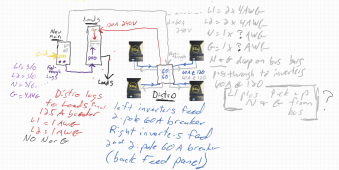
I think I'm getting closer. New Main panel with pass through lugs to existing Loads panel. At Main 2 x 60Amp pass-through distro panel to inverters. Inverters out to distro panel 60A breakers (back fed). Distro panel lugs to Loads 125A breaker with generator inter-lock with 200A breaker.
AC design.png
Any thoughts?
 
"Pass through" means the wires (grey lines) are in the Distro box, but don't land on breakers there, just go the inverters?

4 awg has ampacity 95A, so neutral could see 190A, suggesting 2/0.
60A breaker x 2 = 120A, 2 awg would handle that.
Sizing for the wire not the breaker allows for future larger breakers, and may be code requirement.


Mine is wired in 6 awg. I ran 2 awg Neutral to a panel, and from there 6 awg to a split-bolt splice and branched to 2 inverters opposite phase. I did the 6 awg run a second time for the second pair of inverters.
L1 and L2 run in four 6 awg wires to input of inverters, and in four more 6 awg from output of inverters to the panel.

Originally I had L1/L2/N all in 2 awg direct to the panel, which has GT PV inverters. Now, the neutral works bidirectionally, and the L1/L2 backfeed main panel through an interlock.

For 2/0 wire, 4 awg ground.
For 4 awg wire, 8 awg ground.

My 2 awg and 6 awg both get 8 awg ground.

 
"Pass through" means the wires (grey lines) are in the Distro box, but don't land on breakers there, just go the inverters?
Yes, the load lines will just enter the distro panel then exist and go to the inverters, no breakers. Would it make sense to land neutral and grounds (grey lines) on the distro panel bus bars and grab four neutrals and 4 grounds from the bus bar to pass along to the inverters with the "pass-through" load lines?
 
I fanned out my neutrals that way.
I might have routed them to terminals in the inverter, then on from there, but ran into conduit fill limits (inverters installed after conduit branches in place.) So one wire from main panel to PV aggregator panel neutral bus bar, 2 wires from busbar toward inverters, splice and split to 4 wires for the inverters. Ground routed the same way.
I just had to be careful to map to split phases correctly, so neutral carries difference not sum of L1, L2.

Could be different for an inverter with all-pole disconnect relay, like a mobile inverter, but I determined my two neutral lugs were one net with no measurement or anything else between them.
 
Back
Top