diy solar

diy solar

AC side MPP LV6548 connections, critical load panel, wiring

sethile

New Member
Joined
Dec 29, 2021
Messages
113
This is an off grid installation using a single MPP LV6548. I'm working on a critical loads panel, and trying to plan the AC wiring while waiting for my LV6548.

Two pressing questions I'm trying to research have me confused. In case it is relevant here is a (link to previous thread) discussing the PV side and includes a block diagram and discussion of the set up.

Main AC side questions:
1.
Is it OK to have the grounds and neutrals all bonded between the Main panel, Critical Loads panel, and the LV6548 AC input and output? That seems dicey to me, but it looks like what will happen if I follow what seem to be credible instructions. If so, is there any danger of feedback into the grid when the grid goes down?

Here's the set up as I understand it:
The grounds and neutrals look to be bonded in my main panel.

The instructions I've seen for the critical loads sub panel seem to indicate I should:
  1. run THHN between the ground and neutral buses on main panel to the ground and neutral buses of critical load panel. Note: The critical loads panel only has a neutral buss, no ground buss, but if they are already combined in the main, it seems redundant to add a separate ground buss. Maybe this would solve what I'm concerned and confused about, but I don't see how it would since they are combined in the main panel.
  2. then for each circuit I want to move I would remove the wire from the circuit breaker main panel, splice THHN to the wire
  3. run the spliced wire to the critical loads panel, and reconnect the breaker there.
That made sense to me until I realized the neutrals and grounds of both the AC input and output of the LV6548 would run to both the sub panel and the main panel. And that has me scratching my head.

2. Wire runs:
  • I have the main and critical load panels flush mounted on either side of a stud in the back wall of a cabinet, with a nipple between them.
  • My LV6548, battery, and fused solar disconnect will be in an adjacent closest.
  • I have a nipple going out the other side of critical loads panel (away from the main panel, and toward the closet), and have prepared the studs for a wire run through them in the wall to the wall of the closet.

My confused understanding is I can run NM-B (stranded Romex style cable) in the wall, but can't run it all the way to the LV6548 as that would have it exposed. And I can have SOOW run from the wall to the LV6548, but not in the wall. Is that correct?

If so, the best plan I've come up with is to run 6/3 NM-B from the main panel (50A breaker), through the bottom of the critical loads panel, out the other side, through the wall studs to the wall of the closet where the LV6548 will live. Then connect that to 6/3 SOOW in a junction box, which I can then run out of the wall to the LV6548 AC in.

The LV6548 AC out is connected with 6/3 SOOW back to the junction box, where it connects to 6/3 NM-B, which then runs through the wall and connects to the critical loads panel.

By way of a picture is worth a thousand words (not sure it's going to help much):
AC-side.png


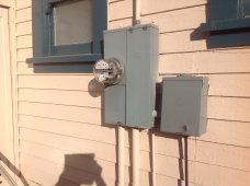
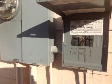
And in case they help, photos of the Main panel, critical load panel, and the massive hole I made in the wall of the closet in order to drill through the studs:

20220207_172245.jpg20220207_172259.jpg20220207_172315.jpg20220207_172357.jpg

Thanks for getting this far! Any thoughts?
 
Last edited:
You only want one bond of the neutral and ground and it should be in the main panel (or the service entrance).

The LV6548 is a 120v unit, no? I would just run three wires (Red (Line), White (Neutral), Green (Ground)) from the main breaker panel directly to the AC in on the LV6548 unit, and then run the same color wires from AC out on the LV6548 to the 120v critical load panel. The manual page below: (I don't like their wire color choice though).

1644358868491.png
 
You only want one bond of the neutral and ground and it should be in the main panel (or the service entrance).

The LV6548 is a 120v unit, no? I would just run three wires (Red (Line), White (Neutral), Green (Ground)) from the main breaker panel directly to the AC in on the LV6548 unit, and then run the same color wires from AC out on the LV6548 to the 120v critical load panel. The manual page below: (I don't like their wire color choice though).

Thanks! That confirms what I thought, but it still seems odd to me. While it makes sense to me to have only one bond of neutral and ground at the main panel, I will need to run the neutral from the main panel (which is already bonded to ground) over to the neutral buss on the critical loads panel. The ground makes the trip with it, right? And all the way through the system. Or am I confused about that?

Yes, run singly like I am LV6548 is 120V. You can run 2 or more together to get 240. And up to 6 in various configurations, including 3-phase! Pretty cool, but mine will only be one unit running 120V for the foreseeable future.

I've poured over the manual, which makes a lot of sense, and the AC connections are straight forward as far as they go. I don't like their wire colors either! I'm hoping to find 6/3 (Red (Line), White (Neutral), Green (Ground)) in both NM, and SOOW.

Thanks again!
 
Thanks! That confirms what I thought, but it still seems odd to me. While it makes sense to me to have only one bond of neutral and ground at the main panel, I will need to run the neutral from the main panel (which is already bonded to ground) over to the neutral buss on the critical loads panel. The ground makes the trip with it, right? And all the way through the system. Or am I confused about that?

I am basing my comment of my LV2424 (smaller version of what you have). You will not drag anything over to the critical loads panel at all. The only thing that should come out of your main panel is the AC line to feed the LV6548 (Hot, Neutral, Ground). Your critical load panel will be fed directly from the LV6548 (again Hot, Neutral, Ground).

If you want to feed the critical load panel directly from the main panel, you need a transfer switch that will remove the LV6548 from the equation, but I don't see a need unless you expect the inverter to fail. If you run out of battery, you can simply use the bypass feature of the inverter to feed grid to the critical panel.
 
The ground makes the trip with it, right? And all the way through the system. Or am I confused about that?
The ground is a separate wire if that is what you mean by "makes the trip with it,". It should be in the same conduit with the neutral or be part of the Romex cable. Did that answer your confusion?
 
I am basing my comment of my LV2424 (smaller version of what you have). You will not drag anything over to the critical loads panel at all. The only thing that should come out of your main panel is the AC line to feed the LV6548 (Hot, Neutral, Ground). Your critical load panel will be fed directly from the LV6548 (again Hot, Neutral, Ground).

Great news, thank you very for confirming this!! It's extremely helpful!!!

If you want to feed the critical load panel directly from the main panel, you need a transfer switch that will remove the LV6548 from the equation, but I don't see a need unless you expect the inverter to fail. If you run out of battery, you can simply use the bypass feature of the inverter to feed grid to the critical panel.
I'm content feeding the critical loads through the LV6548 and letting it manage things, but I can certainly understand why having the option of a transfer switch makes some sense. My plan was to test to LV6548 pretty well before transferring the critical loads. If it seems dependable I'll pull the trigger on that plan. If it seems questionable for some reason, I'll rethink it.

Thanks again!
 
I can certainly understand why having the option of a transfer switch makes some sense.
If you are off grid what would be the purpose of a transfer switch unless it is for a generator? I am not sure why you would want a critical loads panel either. Typically a transfer switch is used to separate the grid from the inverter to protect linemen.

If this is truly an off grid situation the inverter would power the main load panel. A critical loads panel is typically used in a grid situation for when the grid goes down and one would only want to power certain loads (often called critical or essential loads) with a system which might not have the capacity to handle all loads that the grid connection can handle.
EDIT: I reviewing the picture of the main panel it looks like this may be grid connected in which case your would want a transfer switch to isolate the grid at the main panel.
 
Last edited:
The ground is a separate wire if that what you mean by "makes the trip with it,". It should be in the same conduit or be part of the Romex cable. Did that answer your confusion?
Yes, I do get that. Your answer does help solidify it to some extent, though. Thank you.

My confusion has more to do with the bond between the ground and neutral in the main panel, and carrying that bond throughout the system independent of the ground wire by virtue of running a connection between the neutral buss in the main panel to the critical loads panel (if that makes any sense). iamrich 's answers helped clarify that for me.

So, I'm still a little confused, to be honest, but I'm also used to that. I'm cool being confused if I'm convinced the problem is in my head, and I'm not about to fry something or hurt myself or worse, others ;)

If you are off grid what would be the purpose of a transfer switch unless it is for a generator? Typically a transfer switch is used to separate the grid from the inverter to protect linemen.
Exactly... my concern was making sure my "off grid" design was in fact, "off grid", and did not somehow feed back to the grid. It will be tested, but I'd sure like to head that off before I have the inspector from the electric company come to do that ;) I'm also planning to get an electrician buddy out to look things over before I move the critical loads over. Hoping to minimize needing his help while trying not to be stupid...

Edited (to clarify). My solar installation is intended to be "off grid". My home is on grid with solar assist and hopefully back up... I may have some of this terminology messed up...

Thanks again!
 
If you are off grid what would be the purpose of a transfer switch unless it is for a generator? I am not sure why you would want a critical loads panel either. Typically a transfer switch is used to separate the grid from the inverter to protect linemen.
Some people use a transfer switch to isolate the inverter and put the critical load panel back on grid power direct so that the inverter can be serviced without taking the critical load panel offline.
 
Some people use a transfer switch to isolate the inverter and put the critical load panel back on grid power direct so that the invert can be services without taking the critical load panel.
Of course that makes sense but the OP said this was off grid so that was the reason for my reply. Later I looked at the main panel an it clearly was fed by conductors that presumably were the grid connection. For the maintenance that you refer to a simple interlock could be a more cost effective solution. However the code requires some automatic islanding to protect linemen. If the inverter does not have that then an automatic transfer switch would have to be inserted.
 
My confusion has more to do with the bond between the ground and neutral in the main panel, and carrying that bond throughout the system independent of the ground wire by virtue of running a connection between the neutral buss in the main panel to the critical loads panel (if that makes any sense). @iamrich 's answers helped clarify that for me.
Yes is seems counter intuitive that since the ground and the neutral would normally have continuity, but the reality is that the nuetral does carry current and the ground is not designed to carry current. It does not carry current unless something goes wrong and the grounding of all the sub panels and inverters reduces the risk of someone getting shocked if a conductor shorts to ground.

The only thing that I would add to the explanation of @iamrich is that typically a sub panel has two hots, a neutral and a ground. Maybe the inverter you are considering is only 120 volts but I do not know the code implications of feeding a sub panel with only one leg of 240 volts. That is a question your friend or the building official can clarify.
 
Of course that makes sense but the OP said this was off grid so that was the reason for my reply. Later I looked at the main panel an it clearly was fed by conductors that presumably were the grid connection. For the maintenance that you refer to a simple interlock could be a more cost effective solution. However the code requires some automatic islanding to protect linemen. If the inverter does not have that then an automatic transfer switch would have to be inserted.
Yes, the main panel is on grid for sure. I'm pretty sure the LV6548 has automatic isolation built in, but will confirm that.
 
The only thing that I would add to the explanation of @iamrich is that typically a sub panel has two hots, a neutral and a ground. Maybe the inverter you are considering is only 120 volts but I do not know the code implications of feeding a sub panel with only one leg of 240 volts. That is a question your friend or the building official can clarify.
Yes, the inverter in this plan is only 120V. It's possible to have more than one of the LV6548s linked to provide 240V and even 3-phase, but my plan is just the one at 120V. My plan is to jumper the 120V from one side of the panel to the other as I believe is typical in a 120V sub panel. So we should be cool there...
 
This is an off grid installation using a single MPP LV6548. I'm working on a critical loads panel, and trying to plan the AC wiring while waiting for my LV6548.

Two pressing questions I'm trying to research have me confused. In case it is relevant here is a (link to previous thread) discussing the PV side and includes a block diagram and discussion of the set up.

Main AC side questions:
1.
Is it OK to have the grounds and neutrals all bonded between the Main panel, Critical Loads panel, and the LV6548 AC input and output? That seems dicey to me, but it looks like what will happen if I follow what seem to be credible instructions. If so, is there any danger of feedback into the grid when the grid goes down?

Here's the set up as I understand it:
The grounds and neutrals look to be bonded in my main panel.

The instructions I've seen for the critical loads sub panel seem to indicate I should:
  1. run THHN between the ground and neutral buses on main panel to the ground and neutral buses of critical load panel. Note: The critical loads panel only has a neutral buss, no ground buss, but if they are already combined in the main, it seems redundant to add a separate ground buss. Maybe this would solve what I'm concerned and confused about, but I don't see how it would since they are combined in the main panel.
  2. then for each circuit I want to move I would remove the wire from the circuit breaker main panel, splice THHN to the wire
  3. run the spliced wire to the critical loads panel, and reconnect the breaker there.
That made sense to me until I realized the neutrals and grounds of both the AC input and output of the LV6548 would run to both the sub panel and the main panel. And that has me scratching my head.

2. Wire runs:
  • I have the main and critical load panels flush mounted on either side of a stud in the back wall of a cabinet, with a nipple between them.
  • My LV6548, battery, and fused solar disconnect will be in an adjacent closest.
  • I have a nipple going out the other side of critical loads panel (away from the main panel, and toward the closet), and have prepared the studs for a wire run through them in the wall to the wall of the closet.

My confused understanding is I can run NM-B (stranded Romex style cable) in the wall, but can't run it all the way to the LV6548 as that would have it exposed. And I can have SOOW run from the wall to the LV6548, but not in the wall. Is that correct?

If so, the best plan I've come up with is to run 6/3 NM-B from the main panel (50A breaker), through the bottom of the critical loads panel, out the other side, through the wall studs to the wall of the closet where the LV6548 will live. Then connect that to 6/3 SOOW in a junction box, which I can then run out of the wall to the LV6548 AC in.

The LV6548 AC out is connected with 6/3 SOOW back to the junction box, where it connects to 6/3 NM-B, which then runs through the wall and connects to the critical loads panel.

By way of a picture is worth a thousand words (not sure it's going to help much):
View attachment 82978


Thanks for getting this far! Any thoughts?
There is one major mistake in your wiring, you have the ground and neutral bonded togather in the critical loads sub panel, that is not what the NEC wants you to do. You can only bond the neutral buss to the ground buss in the main box only. The sub panel needs to have seperate busses for the neutral and ground. The reason for this is that the ground buss should carry current only in a fault. Connected like you show there would be current on the ground, creating a hazard and possibly nuisance tripping of GFCI devices. You may well have to buy a dedicated ground buss for smaller panels like your sub panel. These are available at electrical dealers. I stock and use Square-D and run into this all the time. Use the same brand as your Bryant panels if you can. The Bryant equivalent of the Square D PK7GTA would be perfect for your application. You do need to use the same brand to keep your U.L. listings for your panels.
 
There is one major mistake in your wiring, you have the ground and neutral bonded togather in the critical loads sub panel, that is not what the NEC wants you to do. You can only bond the neutral buss to the ground buss in the main box only. The sub panel needs to have seperate busses for the neutral and ground. The reason for this is that the ground buss should carry current only in a fault. Connected like you show there would be current on the ground, creating a hazard and possibly nuisance tripping of GFCI devices. You may well have to buy a dedicated ground buss for smaller panels like your sub panel. These are available at electrical dealers. I stock and use Square-D and run into this all the time. Use the same brand as your Bryant panels if you can. The Bryant equivalent of the Square D PK7GTA would be perfect for your application. You do need to use the same brand to keep your U.L. listings for your panels.
Super super helpful, thanks! And that is something I suspected! I saw that separate ground buss for the sub-panel mentioned in the installation guide, and will implement it. Thank you very much!!
 
It is perfectly acceptable to every inspector that I have dealt with to use the Bryant sub panel as 120 volt only, Use one breaker from the inverter output and “back-feed” it from the inverter and jumper L1 and L2 togather at the top as in your drawing, this is legal and acceptable
 
There is one major mistake in your wiring, you have the ground and neutral bonded togather in the critical loads sub panel, that is not what the NEC wants you to do. You can only bond the neutral buss to the ground buss in the main box only. The sub panel needs to have seperate busses for the neutral and ground.
OK, I think I'm on the right track and checking to make sure.

The instructions I've seen for the critical loads panel (if I understand them correctly) include linking the neutral buss in the main panel to the neutral buss in the critical loads panel, and linking the ground buss in the main panel, to the ground buss in the critical loads panel.

Is that still the correct procedure even though the neutral and ground are bonded in the main panel?

If that's still the way to do it, the following diagram should now be correct. Please give it a peek if you get a chance.. It's a little tough to see at this scale, but it should be consistent with my current understanding of not bonding the neutral and ground busses in the critical loads panel. To accomplish this I will be adding the Eaton Load Center Ground Bar Kit Model #GBK10CS.

Thanks very much!

AC-side.png
 
That is exactly what is specified in the NEC. This will pass inspectors code on that issue and be safe.
 
That is exactly what is specified in the NEC. This will pass inspectors code on that issue and be safe.
Fantastic!! Thank you very much!! I feel a ton better having you confirm that, and really appreciate your help!
 
Looking again, I do not understand why you have a breaker from the main box feeding a breaker in the sub panel.

This is not correct as it will directly short the input of the inverter to the output of the inverter. The output of the inverter feeds the main breaker in the sub panel. L1 and L2 of the sub panel are shorted together to make this a 120 volt panel, there should be no jumper from here to the inverter output.

If you want to do a bypass switch for inverter service there would need to be 2 main breakers in the sub panel interlocked so that only one could be on at any one time.

Square D does have such a breaker interlock but AFAIK Eaton does not have any such “dual feed breaker interlock”

Am not familiar with your inverter/charger but most have a power feed through relay which connects inverter/charger input to the output to provide “feed through” power in case of inverter shut down or failure.

Photo shows a Square D QO8-16L125S panel with the “dual source” breaker interlock feature installed. Not exactly the same situation , This one is a farm office where the panel on the left is the POCO main panel (Square D Homline HOM12/24M125S) The right panel is the critical loads panel which can be fed from the Homeline panel OR the backup generator

Square D does have the widest range of product’s available so that is why Im a stocking Square D installer....I only stock panels to install, I am not a reseller of panels
 

Attachments

  • 61DC7411-C9EE-46B8-A794-BE14FEDE2961.jpeg
    61DC7411-C9EE-46B8-A794-BE14FEDE2961.jpeg
    557.4 KB · Views: 19
  • 01420D90-F17A-49E3-BDAF-358B03A34363.jpeg
    01420D90-F17A-49E3-BDAF-358B03A34363.jpeg
    549.2 KB · Views: 19
Back
Top