diy solar

diy solar

AC side MPP LV6548 connections, critical load panel, wiring

I've been reading through this thread, numerous times, and have had many of the same questions.

I am using a single LV6548, off-grid, with a generator for AC input into the LV6548.
200 amp breaker box from the LV6548 AC out.
100 amp sub-panel to our cabin from the 200 amp box.
From what I've read lately, I was planning on keeping the grounds and neutrals separate in the 200 amp box and the sub-panel as well as not touching the bond screw inside the LV6548.

Will also add a bonding plug to the generator.

This is getting done in stages. The solar panels will be installed this fall.

I've seen several different ways to properly wire this all. This is what I've ended up with currently. If someone thinks I'm screwed up, I would appreciate you letting me know.
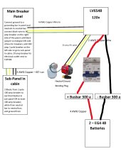
Looking to make sure I am wiring my LV6548 correctly2.jpg
 
Last edited:
The 4 AWG and 2 AWG are not large enough. With a 6.5K rated inverter, you would see up to 140A DC under normal full load conditions. 1 AWG or 1/0 AWG would give you the needed capacity.

As for the main breaker panel and subpanel, I would assume this is in a separate structure from the cabin and you might add another LV6548 later giving you 240V split phase if desired. The main panel in the separate structure will need a ground rod connected to grounding busbar and another at the subpanel at the cabin.

The main panel breaker from LV6548 should be sized for inverter max output, 60A. The breaker feeding the subpanel should actually be 30A for a double pole as you are splitting the inverter output. You can oversize the wire for later expansion and change to a larger breaker in the future. Running a 100A or larger breaker off the inverter output could lead to a possible inverter failure if both sides of the subpanel were to pull 30A from each half of the subpanel.

If you were to add a second LV6548 now, you could run the full 60A on each phase or in parallel at 120V. Personally, I would wire for split phase as this allows 60A per each half on 240V split phase for a total of 13Kw compared to only half that on 120V with inverters in parallel and wired with splitting at the main panel. Your needs in a cabin may not be that large however considering your have only a 120V generator.
Thanks @Zwy ! There are only 3 wires for the AC out from the LV6548. L, N, and G. That's where I was getting confused as well because most people are using 2 inverters and have the two Lines (one from each inverter) going into the main panel 2-pole breaker. I watched Will's most recent video, which was great but wasn't sure how I could do 2 Lines into the breaker when there is only one Line from the Inverter.

Also, you are correct. Everything is going into my shed to keep it separated from the cabin. I don't really anticipate ever needing 100 amps in the cabin, but thought I should just do the 100 amp just in case.

Will was also using the 4 AWG from the batteries to the bus bar and I saw some people using 2 AWG from the inverter to the main panel, but I've seen a lot of different setups that do totally different things.
 
The main panel breaker from LV6548 should be sized for inverter max output, 60A. The breaker feeding the subpanel should actually be 30A for a double pole as you are splitting the inverter output. You can oversize the wire for later expansion and change to a larger breaker in the future. Running a 100A or larger breaker off the inverter output could lead to a possible inverter failure if both sides of the subpanel were to pull 30A from each half of the subpanel.
This is what I would do as well.

Also, you are correct. Everything is going into my shed to keep it separated from the cabin. I don't really anticipate ever needing 100 amps in the cabin, but thought I should just do the 100 amp just in case.
You want to protect the output of your inverter from the sub panel. Better to pop a properly sized breaker than a fuse(s) (or worse) in the inverter.
Will was also using the 4 AWG from the batteries to the bus bar and I saw some people using 2 AWG from the inverter to the main panel, but I've seen a lot of different setups that do totally different things.
Do you have this backwards maybe? I think you can probably get away with 2awg at the batteries (6550w / 48v = 135a, Copper 2awg =131a), and 4 awg should be fine from the inverter to the panel (6500 / 120v = 55a, copper 4 awg = 92a).
 
Will was also using the 4 AWG from the batteries to the bus bar and I saw some people using 2 AWG from the inverter to the main panel, but I've seen a lot of different setups that do totally different things.

MPP recommends 4 AWG for both the LV6548 AC input and output terminals. I used 6 AWG SOOW stranded and could barely cram them in there (Will mentioned the same thing in one of his videos covering these units).

Even using 6 AWG I ended up braking one of the terminals in the process. You might get 4 AWG solid in these terminals, but I doubt very much you'd get 4 AWG stranded or larger in there unless there is some special technique I'm not aware of.

I used 1/0 for the battery connections. But my set up is considerably different than yours is.
 
This is what I would do as well.


You want to protect the output of your inverter from the sub panel. Better to pop a properly sized breaker than a fuse(s) (or worse) in the inverter.

Do you have this backwards maybe? I think you can probably get away with 2awg at the batteries (6550w / 48v = 135a, Copper 2awg =131a), and 4 awg should be fine from the inverter to the panel (6500 / 120v = 55a, copper 4 awg = 92a).
Thanks @iamrich
I thought the size wire was backward, but thought that's what Will did on his setup.
I think I am finally getting going in the right direction now.

I emailed MPP Solar as well and it seems that this last layout is what they would recommend as well.

Thanks again!
 
I have to say, Ian is very quick with his responses. I do appreciate that!
I asked him about what he suggests and he indicated DC ground fault devices. He stated:

"If its using ground as only a reference, just to detect impalance between + and – then no polarity bonding to G would be required."

I believe this is your "method 2" for ground fault detection. Now I cannot figure out if this is true (ie no bond), and your diagram for this indicates "solidly grounded" between the equipment ground and the grounded conductor, so perhaps it is not.

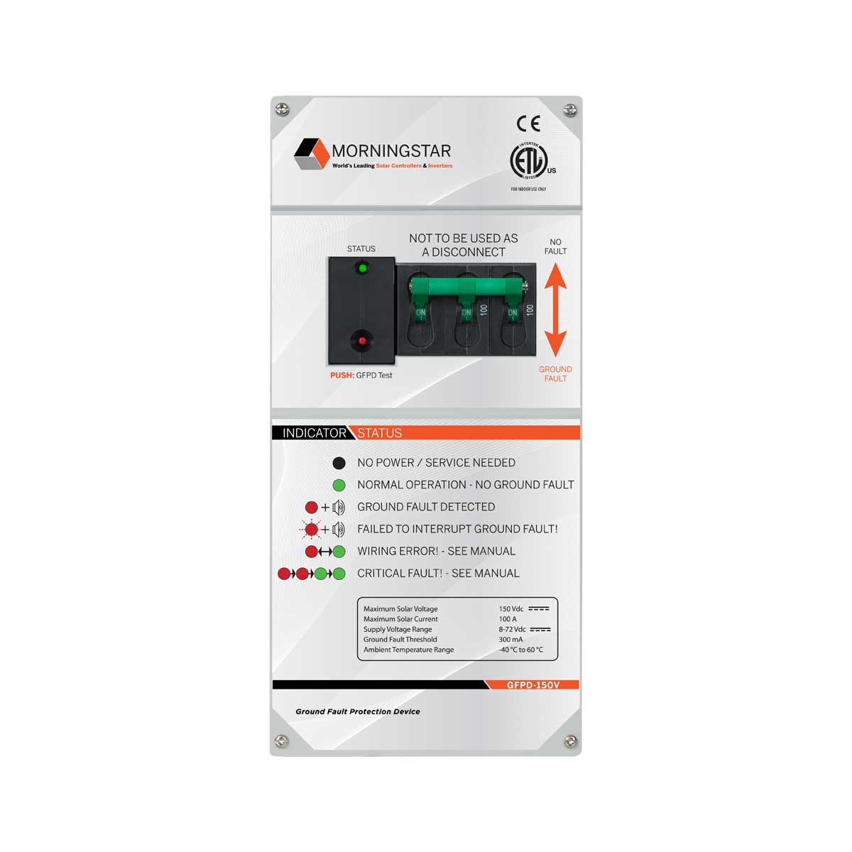
Let's maybe look at an example that won't break the bank, although it's not as cheap as I was hoping to get this accomplished. The "MORNINGSTAR GROUND FAULT PROTECTION DEVICE 600V". Located here:

Would this require a bond between the equipment ground and the grounded conductor? if not, would it be a solid choice for my situation? Right now 250V and around 18A.

I can't say it enough how much I appreciate your help. Thank you!

Was just curious if this is what you went with for your PV Ground Fault Solution? I'm still looking for a solution for both ground fault and arc fault for my setup.
 
Was just curious if this is what you went with for your PV Ground Fault Solution? I'm still looking for a solution for both ground fault and arc fault for my setup.

So, in asking around, I was talking to one of the engineers at Northern AZ Wind and Solar and he said that the MorningStar solution wouldn't work and then added the following:

"So just an FYI... Pretty sure with these inverters if you have a low resistance bond between PV negative and ground you will damage the HV DC Bus... They are pretty much garbage at that point. So be careful with your solution..."

With that said, what other options are there for 3rd Party Ground Fault Protection?

Also, how can the EG4 6500 and similar LV6548 type inverters be TUV or UL certified without Ground Fault and Arc Fault protection?
 
Was just curious if this is what you went with for your PV Ground Fault Solution? I'm still looking for a solution for both ground fault and arc fault for my setup.
I'm still considering it. I haven't done it as of yet as I've had some other things to take care of first such as getting my roof setup properly.
 
I'm still considering it. I haven't done it as of yet as I've had some other things to take care of first such as getting my roof setup properly.

Gotcha - saw the approved diagram that you posted a while back - wasn't sure if you finished building the system / got it inspected. Definitely interested to see how things work out / what you settle on that passes.
 
make those every time I try to hang a gate
Ya. They are zinc plated which is a benefit…
I’d be like you and make them. Acetylene torch, a forge, or a TiG set low enough to not puddle and a bench vise would do it.

I’m vertical mounted to a wall with pressure treated 2x4. Seemed like a good idea at the time but those hinges and some metal (or diy hinges and metal) are more confidence inspiring.
3 panels on the side of the garage facing south (even at 80 or 70 degrees) outweighs I think even 5 panels on the north side. I think even with no tilt (90 degrees) they are better than 4 on the north side.
Hmm. Thanks for this.
Did you end up removing the bonding screw?
I am here for that situation. Supplier of 6548 said to remove screw and jumper in/out but I’m reading this thread to confirm but developed doubts instead.
You might get 4 AWG solid in these terminals, but I doubt very much you'd get 4 AWG stranded or larger in there unless there is some special technique I'm not aware of.
wow. That’s no good. I have 4AWG THHN for this.

~ ~ ~ ~ ~ SEGUE ~ ~ ~ ~ ~​

I am formulating some questions for a thread. After reading all this I’m wondering if I shouldn’t post here.
Lots of good information​
 
Back
Top