diy solar

diy solar

Active balancer, make it smart!?

Vi s

Learning
Joined
Dec 6, 2020
Messages
340
Location
Thailand
Hello DIYer

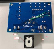
Have you also experienced that your non-smart cheap active balancer (example picture attached) causes your painstakingly top-balanced battery to loose its top-balance over time!?

After some research i noticed that so many others experienced this annoyance as well. Unfortunately i couldn't find a better solution for this issue than connecting the active balancer at around 3.4V and disconnecting it again once the pack is fully top-balanced.
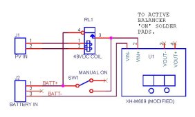
So i wonder if any of the smart guys here came up with something more elegant/ convenient? Maybe an automated way to switch this balancer on and off at certain target voltages!?
Please don't hesitate to share whatever solution you came up with!!

Best regards

News and Updates:
- Here an illustrated explaination about one of the reasons why your battery looses its top-balance because of the active balancer.
- I did contact HANKZOR and asked if they would be able to customize one of their active balancers to start balancing at 3.4V instead of 3.0V like the stock version.
Eventually the kind customer agent promised to talk to the factory to customize one active balancer first. He promised he will come back to me again once the customisation is done. Fast Forward today 6Jun the customized version was finally shipped to me. Will take 9-16days to arrive. Will update once tested.
So let's see, maybe there will be soon an active balancer available which doesn't cause imbalance anymore out of the box, with no workaround needed!
 
Last edited:
The leap frog type active balancers only have a comparator to decide which adjacent pair of cells have the greater voltage. They have overlapping pairs of cells and just shuffle charge up and down the series stack of cells. If you did stop one pair from shuffling up or down based on the two cells it controls it would break the shuffle chain.

This is only one of several methods. It would be dependent on given active balancer.
 
Many thanks for this interesting information!

Is this a leap frog type one?
IMG_20220518_191711.jpg

These are the generic ones i was referring to.

Interestingly there is a RUN solder bridge on this particular active balancer version. I suppose you could install there a switch. Question how to trigger that switch?? How to know that one of the cells is above a certain voltage and start the balancer or below a certain voltage and stop the balancer? Is there an easy way to do that?
 
Last edited:
If you really want to make it smart and you have a smart BMS with UART/RS485 port, you could probably read the cell voltages using an Arduino or something similar, and then turn on the the switch (using a relay or simple transistor).

I think that there is a library for arduino to communicate with JBD/Overkill BMSs over UART, so it should be fairly easy.

The only downside to this is that you will have to give up on the Bluetooth dongle, as it occupies the UART port on the BMS.
 
Just came across this excellent video! This seems already like an easy cheap quick almost ready made solution i was looking for! ?

Just need to figure out how to hook it up on the RUN solder joint!

*Edit: this analog solution works (read further) and there are cheaper and less energy hungry modules out there in compare to the one used in the video.
 
Last edited:
If you really want to make it smart and you have a smart BMS with UART/RS485 port, you could probably read the cell voltages using an Arduino or something similar, and then turn on the the switch (using a relay or simple transistor).

I think that there is a library for arduino to communicate with JBD/Overkill BMSs over UART, so it should be fairly easy.

The only downside to this is that you will have to give up on the Bluetooth dongle, as it occupies the UART port on the BMS.
Thank you, that's possibly the way how to transform a JBD + active balancer into a "JK BMS"!
I also believe what you outlined is possible but unfortunately i know that i am not smart enough to figure that out by myself.
 
IMG_20220518_204437.jpg
IMG_20220518_205257.jpg

Simple small one for less than 1.5 USD inclusive shipping here in my local online store.
Other low voltage disconnect modules draw double the power, some even up to 1.5w!!

*Edit: not recommended because goes into hysteresis
 
Last edited:
This is what I have for 48 volts system. 'ON' in schematic is the same as 'RUN' in the active balancer.
Bench tested OK so far. Got the idea from Andy's Off Grid Garage. It is intended to operate only if there is PV voltage. Modification isolates the relay contacts (Vout). Also added a trimpot, to make readout match with my DMM.
 

Attachments

  • Active Balancer ON-OFF.jpg
    Active Balancer ON-OFF.jpg
    34.2 KB · Views: 75
  • Active Balancer ON-OFF Picture.jpg
    Active Balancer ON-OFF Picture.jpg
    146.1 KB · Views: 70
Last edited:
With this simple mod we (who own a BMS other than from jk) don't need to switch to the jk BMS anymore because of the active balancing issue! This cost-effective solution saves us a lot of money. Of course if you don't have yet a BMS then i would go straight with the jk. Is a cleaner and neater solution.
 
I did this some years back on my 48v battery pack. Essentially I got a bank of 17 interface relays (6a rated), wired the balancer through it, and turned it on only when they battery is above 98% SOC.
 
This is what I have for 48 volts system. 'ON' in schematic is the same as 'RUN' in the active balancer.
Bench tested OK so far. Got the idea from Andy's Off Grid Garage. It is intended to operate only if there is PV voltage. Modification isolates the relay contacts (Vout). Also added a trimpot, to make readout match with my DMM.
Excellent!

Could you probably draw an easy schematic how to connect the following module with the active balancer!? Would be super kind of you because I am not so sure...
IMG_20220518_210821.jpgIMG_20220518_210650.jpg
 
I did this some years back on my 48v battery pack. Essentially I got a bank of 17 interface relays (6a rated), wired the balancer through it, and turned it on only when they battery is above 98% SOC.
That sounds interesting, could you kindly explain a bit more how you did that!? Could you maybe also post a picture to illustrate it?
 
Excellent!

Could you probably draw an easy schematic how to connect the following module with the active balancer!? Would be super kind of you because I am not so sure...
View attachment 95031View attachment 95032
I am assuming that module connects the load to the battery when the relay closes. I think it has to be modified to safely connect to the 'RUN' pads of the active balancer. So, I will need to get my hands on one to trace the connections to cut. I can post modification pictures if what I did on the XH-M609.
 
This is what I have for 48 volts system. 'ON' in schematic is the same as 'RUN' in the active balancer.
Bench tested OK so far. Got the idea from Andy's Off Grid Garage. It is intended to operate only if there is PV voltage. Modification isolates the relay contacts (Vout). Also added a trimpot, to make readout match with my DMM.
So if i understood you correctly, this is the same (stops or doesn't work if below a certain voltage like 3.5v per cell) with the addition that this smart balancer only works if there is also solar power available!?
 
I am assuming that module connects the load to the battery when the relay closes. I think it has to be modified to safely connect to the 'RUN' pads of the active balancer. So, I will need to get my hands on one to trace the connections to cut. I can post modification pictures if what I did on the XH-M609.
The 609 works essentially the same (relay opens/cuts off if goes below certain voltage) so those modification pictures should be sufficient to hopefully get the principle across to me. :)
 
Last edited:
So if i understood you correctly, this is the same (stops or doesn't work if below a certain voltage like 3.5v per cell) with the addition that this smart balancer only works if there is also solar power available!?
Because the module consumes about 1.5 watts, the 48V relay removes power from the module if no solar power is available to charge the batteries. If there is solar power, the module operates in LVD mode, monitoring the battery voltage while being charged by solar.
 
I am assuming that module connects the load to the battery when the relay closes. I think it has to be modified to safely connect to the 'RUN' pads of the active balancer. So, I will need to get my hands on one to trace the connections to cut. I can post modification pictures if what I did on the XH-M609.
Yes, that module cuts the load if it goes below set voltage like the 609, other than that the relay is closed (battery stays connected to load).
 
Because the module consumes about 1.5 watts, the 48V relay removes power from the module if no solar power is available to charge the batteries. If there is solar power, the module operates in LVD mode, monitoring the battery voltage while being charged by solar.
Got it, thank you.
 
The 609 works essentially the same (relay opens/cuts off if goes below certain voltage) so those modification pictures should be sufficient to hopefully get the principle across to me. :)
This is what I did(copper trace cuts) to isolate the relay contacts.
 

Attachments

  • M609 BOTTOM.jpg
    M609 BOTTOM.jpg
    228.6 KB · Views: 48
  • M609 TOP.jpg
    M609 TOP.jpg
    202.2 KB · Views: 48
Back
Top