diy solar

diy solar

Active balancer, make it smart!?

If that delta (at 56.4 and 48) is without a balancer than i wouldn't even use one! ? Amazingly matched cells!

Agreed, that's an exceptionally well balanced/matched pack. The voltage delta is so low that an active balancer wouldn't be doing anything, even if it was turned on.
 
If that delta (at 56.4 and 48) is without a balancer than i wouldn't even use one! ? Amazingly matched cells!

Sure, right now (subject to change) charge stop at 55.2v (because we have a runner cell but maybe the a30 and the new threads (a few were stripped) will hopefully reduce that issue) with 0.5h absorbtion (to avoid instant discharge once 55.2v is hit). These particular values are due to our circumstances, especially because of the inverter and its lead acid charge profile (no lithium profile unless you have a bms which can talk to the inverter). Battery pack 10.2mOhm, 0.6 to 1mohm per busbar.

Balancer goes on at 3.4v (54.4v to catch runner cell) and off at 54V. So far float charge at 54.1v (otherwise the battery gets discharged). Our inverter is only a few weeks old, still in the observation, learning and adaptation phase till the optimal settings for our circumstances and needs are found.
I let the pack float above balance stop rate for a few days then began cycling it for about a week. Pack is really tuned right now and happy with results. Good luck with that runner. PITA to deal with sometimes.
 
Agreed, that's an exceptionally well balanced/matched pack. The voltage delta is so low that an active balancer wouldn't be doing anything, even if it was turned on.
Took some effort to get there with the help of the controller/balancer and some patience.
 
I let the pack float above balance stop rate for a few days then began cycling it for about a week. Pack is really tuned right now and happy with results. Good luck with that runner. PITA to deal with sometimes.
Thanks!
 
What kind of cells are you using?
This is my test battery bank which has been rock solid. Got these from batteryhookup a while ago. Not many full cycles on them (76) because they are not in full time use.
 

Attachments

  • IMG_2054.png
    IMG_2054.png
    1,016 KB · Views: 4
  • IMG_2053.png
    IMG_2053.png
    718.3 KB · Views: 4
I think I found a fairly simple solution for making active balancers turn on automatically:

My idea was this: Use a small transistor as the switch for the active balancer. This transistor will turn on when it's base pin will get enough voltage. As transistors usually have some sort of forward voltage (like a diode) that has to be overcome in order to switch on, we can simply use a voltage divider on our battery pack, connected to the base pin. Usually this is around 0.7v.

The easiest way to do this, is use a potentiometer (pot) with all three pins in use, like this:
potentiometer.png
GND and VCC go to our battery main negative and positive respectively.
Output goes to the base of the transistor.

Now we can calibrate our pot, to output at least 0.7v when our pack voltage rises above a certain threshold.

So I put my theory to the test and it's seems to work!

But before you go run and do this, please read through my experiment and implementation (use at your own risk!).

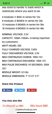
I recently got some of these small (1.2A) active balancers from Aliexpress:

For my experiment I used the 4s model, which is suitable for Li-ion and Lifepo4.
I got these because they are low cost and have a switch option (like the "RUN" pads on the bigger Heltec active balancers).

I did this experiment on a 4s 21700 battery holder with built in BMS which has passive balancing (also from Aliexpress).
I soldered the wires from the balancer to the BMS (B- for the negative wire, and four cell wires to each cell pad respectively).
I check to see that everything is working and that the balancer turns on.

Then I removed the cells from the holder and did a continuity test between the switch pads and the 5 leads and found out that the switch pad is connected to cell 1 (basically powering the PCB from the first cell). Note that this might be different on other balancers, so do your homework first!

I had to cut the tiny trace that was in between these pads (they chose to put a small trace between them, rather that just soldering them together like Heltec does on the RUN pads).

I then took an NPN transistor I had at hand (2N2222a) and soldered the "collector" pin to the first pad which is connected to cell 1, and the "emitter" pin to the other pad (the one going to the circuit).

I then took a 10kOhm pot, and connected the outer pins to B- and B4 (each to its own).
I soldered a 100kOhm resistor to the output (middle) pin of the pot, just for added safety, making sure the base pin of the transistor won't pull too much current.

Before soldering the output with resistor to the base pin, I calibrated the pot like this: With cells removed (!) I connected my PSU to the respective outer pins of the pot (using crocodile clamps) and put my PSU to output 16.0v, which is when I want the active balancer to start (4.0v per cell for Li-ion).
I then measures voltage between Negative and the output, to see what voltage I was getting from the pot (acting as a voltage divider). I slowly turned the pot untill it reached 0.7v.
Then I soldered the output wire (with resistor) to the base pin of the transistor. Inserted the cells again, and made sure no shorts or any smoke are present.
The balancer was off because my total pack voltage was around 15v.

I then connected a charger to the pack, charging slowly and long behold the balancer came on when 16v was reached!

You might have to tweak your pot a bit to get the exact voltage you want, but it works.
You also need to make sure what kind of switching you balancer does (if the switch is on the positive or negative side). Also make sure your transistor is rated properly for your voltage.

The pot is 10k like I mentioned. As it's always connected to the pack, It draws 1.68mA which is not bad. If you want to lower this even more you might need to search for a higher resistance pot.

I hindsight, maybe I shouldn't have connected the pot to the battery negative. Rather I should have connected to the BMS P- port, to avoid the pot discharging the battery all the way down.
This will also give some more protection if there is a short. Maybe a small fuse could have been used too.

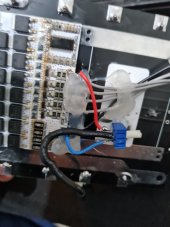
So here are some pictures.
It's a bit of a sloppy job, because this was just for experimenting, just to prove that it works.

20230512_152028.jpg20230512_152034.jpg20230512_152044.jpg
 

Attachments

  • 20230512_152048.jpg
    20230512_152048.jpg
    107.7 KB · Views: 9
Last edited:
Quick and dirty, I like it.
I wonder whether the transistor will fluctuate between the on and off states rapidly as the battery teeters around its threshold voltage during charge or discharge? Using a Schmitt trigger instead of a bare transistor would avoid this as it provides a definitive on and off state with some added hysteresis.
Wasn't familiar with that component, I'll look into it, thanks !
 
Wasn't familiar with that component, I'll look into it, thanks !
And thank you for the link to the balancer you're using. I wasn't aware this type existed, it's perfect for another project I'm working on. I've ordered one and will report back on how it performs.

The usual cheap inductive balancers based on the ETA3000 have some annoying flaws that make them nearly useless for LiFePO4. The type you linked to are just as cheap and might be a good alternative.
I haven't tested this balancer thoroughly yet. Just some testing and playing around. It does work though. But the maximum current I've seen for a cell is 250mA. I'm not sure if that's because the imbalance wasn't high enough, or if that just what it gives. It's unclear from the specs whether the 1.5A balance current is for each cell (as expected) or total for all cells (which is kinda disappointing).

I was also expecting some LEDs to flash/turn on when actual balancing happens, like some other balancers (as shown on one of Wills older videos), but there aren't any. Just one power LED.

But I do like the compact size and the fact that it can be switched off. Some of the balancers I've seen on Aliexpress don't have a switch function. So we can't hack them that easily...
 
Last edited:
Back
Top