diy solar

diy solar

Active balancer, make it smart!?

Good catch. I learned in the meantime, that 3.37 V is the "magic" number for the LFP cell to turn on the active Balancer. Reason: Even for the lowest possible charging current, 3.37 V indicates a full cell with SOC = 100%. I played around with low and high charging currents (I = 0.5 C) and recorded cell voltages during full charge / discharge cycles. I ended up with 3.37 V balancer On, and 3.34 V balancer Off being a good match.
My KISS System produces a maximum balancing current of 4 A. The current is proportional to the voltage difference of the cells (same is true for the Heltec 5 A balancer). Due to the fact, that the balancing current becomes zero, once all cells are balanced, one can be sure, that the balancer reads actual cell voltages not being affected by a voltage drop at the balancer wires!
As promised I will get you some circuit diagrams next week.
Regards Hans
Appreciate and value these information!

Vielen herzlichen Dank!
 
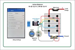
As promised, here is one option how to control the Heltec active Balancer using the BMV712 Battery Monitor........I will show more circuit diagrams on this subject later this week.
Regards Hans
p.s. it is easy to modify this circuit for 24 V ....36 V ..... 48 V Systems, using the appropriate balancer from Heltec
BMV712 Einbeziehung.jpg
 
Last edited:
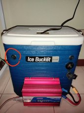
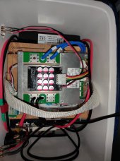
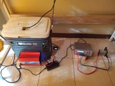
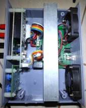
Two days ago i finally installed a switch for the balancer which alone already increased convenience by a lot. Now i don't have to open and close the box as well pull or push in the balancer cable again anymore.
Relay solution going to come next.
IMG_20220531_222226.jpgIMG_20220531_222320.jpg
 
As promised, here is one option how to control the Heltec active Balancer using the BMV712 Battery Monitor........I will show more circuit diagrams on this subject later this week.
Regards Hans
p.s. it is easy to modify this circuit for 24 V ....36 V ..... 48 V Systems, using the appropriate balancer from Heltec
View attachment 96541
great diagram!!
 
Two days ago i finally installed a switch for the balancer which alone already increased convenience by a lot. Now i don't have to open and close the box as well pull or push in the balancer cable again anymore.
Relay solution going to come next.
View attachment 96544View attachment 96545
Hi Visusolar, you plan to do the next step, which is the relay version. Before I will post more circuit diagrams to drive the Heltec active balancer (some of which require assembling of electronic components on a PCB), I thought about the usage of cheep modules. Some modules have been addressed in the previous discussions.
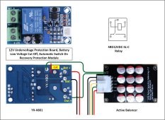
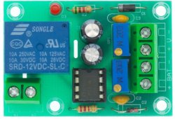
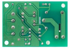
I ordered an undervoltage protection module YX-X801, and I expect it to arrive by tomorrow. I will test this module to find out how to connect it to the balancer.
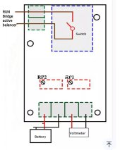
Here is the circuit diagram, which i will try first.
YX-X801.jpg
If all goes well, I will present my findings at the end of this week.
Regards Hans
 
Hi Visusolar, you plan to do the next step, which is the relay version. Before I will post more circuit diagrams to drive the Heltec active balancer (some of which require assembling of electronic components on a PCB), I thought about the usage of cheep modules. Some modules have been addressed in the previous discussions.
I ordered an undervoltage protection module YX-X801, and I expect it to arrive by tomorrow. I will test this module to find out how to connect it to the balancer.
Here is the circuit diagram, which i will try first.
View attachment 96747
If all goes well, I will present my findings at the end of this week.
Regards Hans
Hallo Hans
I also saw this particular module. I chose the XH-601 over the YX-X801 because it was half as "expensive" and seemed to be usable without having to modify it. Downside was not available locally so i am still waiting for it to arrive.
Looking forward how well the X801 module will work!
How big is the voltage error in reality? According to the specs of these cheap modules ±0.1V.
Best regards
Max
 
Hallo Hans
.......
How big is the voltage error in reality? According to the specs of these cheap modules ±0.1V.
Best regards
Max
Hi Max,
this Module has separate settings for the voltage level for switch on (of the balancer), and for switch off. It is difficult to predict how accurate these settings will be over temperature and time. I will try to extract as many details as possible, once I have the module in my lab. I will let you know once I have analysed the module.
Just give me a little time
Regards Hans
Hallo Hans
That sounds great!
No hurry please take all the time you need.
Looking forward to your findings while tinkering with it.
Judged by professional experienced eyes, have you noticed anything missing (design flaw) with the 601 module on first glance? I see there are much less components in compare to the x801 but that is also partly because of the additional force start switch terminal function of the x801 and leds.
Do you think the x801 is much better since it has different (more accurate/fitting?) potentiometers? Should i also order that one to take part in the tinkering fun!?
Best regards
IMG_20220602_053800.jpg
IMG_20220602_053817.jpgIMG_20220602_053800.jpg
 
Last edited:
Hi Max,
this Module has separate settings for the voltage level for switch on (of the balancer), and for switch off. It is difficult to predict how accurate these settings will be over temperature and time. I will try to extract as many details as possible, once I have the module in my lab. I will let you know once I have analysed the module.
Just give me a little time
Regards Hans
Dear Hans,
Thank you for what you have already done.
Thank you for what you might do!
Cheers. Will try here too. Active balancing is a very interesting topic!
 
Good news, there is some progress concerning the customized version (goes to sleep if cell goes below 3.4V, starts balancing at about 3.4V) from HANKZOR:
IMG_20220602_083834.jpg
I still have to pay the full price for it (not a free sample) but no additional costs at least. But their prices are higher than other shops by quite a bit. :/

Unrelated to that i started the lengthy process to check the capacity and internal resistance of all my 14 32650 cells with a EBC-A05+ battery meter to match them later. All done with green energy ? ?
The nice thing of the ebc tester is you can also program and run an automatic discharge test without having to run a PC along side with it. Really like this small tiny light version battery tester.
IMG_20220609_163841.jpg
IMG_20220609_170057.jpg
*Suppose you like to also see how its inside looks like.

So i thought i am going to test this customized active balancer from HANKZOR with one of the upcoming newly matched 12V 5Ah lifepo4 packs. Doing so will speed up the tests i plan as well for safety reasons in case the sample unit behaves unexpected.

Will perform the same automated programed simulation (various different charge and discharge cycles) with and without customized balancer connected.
During those tests we will hopefully also see how much additional energy the balancer and balancing actually uses (my own curiosity).
If it performs as intended and without an issue then i will finally connect it to the 54ah battery of my solar system to test it in real life over the course of days/weeks.

Will keep you updated how this customized version fares! As i have seen and read, most program their smart balancers around 3.4V so what else would you need if this cheaper alternative works like them!? Guess i will also compare it to the upcoming relay solution! :)
 
Last edited:
Good news, there is some progress concerning the customized version (goes to sleep if cell goes below 3.4V, starts balancing at 3.4V) from HANKZOR:
View attachment 96863

Unrelated to that i am right now measuring the capacity and internal resistance of all my 32650 cells with my EBC-A05+ battery meter.
View attachment 96864
View attachment 96865

So i thought i am going to use one of my newly matched 12V 5Ah lifepo4 packs to test the customized active balancer from HANKZOR with. Doing so i will be able to run through a few test cycles much faster (to not keep you waiting to much) as well for safety measures in case the sample unit has an unexpected issue.
Will perform the same amount of cycles, same charge and discharge profiles (automated programed tests with the EBC-A05+) with and without balancer connected.
Will test different scenarios as well check how much additional energy the balancer and balancing uses.
If it tests well then i will connect it to the 54AH battery of my solar system to test it in real life over a few weeks.
Will keep you updated about the results of those tests!
thank you for this update and for pursuing this feature

reserving active balancing for above 3.4V really does seem like a good way to approach LiFePO4 cells.
 
Good news, there is some progress concerning the customized version (goes to sleep if cell goes below 3.4V, starts balancing at 3.4V) from HANKZOR:
View attachment 96863

Unrelated to that i am right now measuring the capacity and internal resistance of all my 32650 cells with my EBC-A05+ battery meter.
View attachment 96864
View attachment 96865

So i thought i am going to use one of my newly matched 12V 5Ah lifepo4 packs to test the customized active balancer from HANKZOR with. Doing so i will be able to run through a few test cycles much faster (to not keep you waiting to much) as well for safety measures in case the sample unit has an unexpected issue.
Will perform the same amount of cycles, same charge and discharge profiles (automated programed tests with the EBC-A05+) with and without balancer connected.
Will test different scenarios as well check how much additional energy the balancer and balancing uses.
If it tests well then i will connect it to the 54AH battery of my solar system to test it in real life over a few weeks.
Will keep you updated about the results of those tests!
HI Max,
Thank you for sharing this information!
I tried last year to convince Heltec to modify the 12 V active Balancer (same as Hankzor) such that it turns on at 3.4 V with a tolerance of +0.00 V / - 0.05 V......but with no success. During this conversation I learned, that it is only one cell being checked for the turn On voltage. I also learned that it is difficult (if not impossible) to meet requirements for a tight setpoint tolerance.
In the meantime I am leaning towards the idea to use the overall battery voltage to turn on the Balancer at 13.5 V, and turn it off at 13.4 V. I have run multiple tests with high and low power charging / discharging. I used various off the shelf modules as well as individual circuit designs to control the Balancer. One example is described in a previous posting.
I am looking forward to your experience with the modified Hankzor modules, in particular the accuracy of the switch On / Off voltage level.
Regards Hans
 
Last edited:
thank you for this update and for pursuing this feature

reserving active balancing for above 3.4V really does seem like a good way to approach LiFePO4 cells.
I think so too. Before I started this thread i was desperately looking for a cheap smart active balancer since the standard active balancer totally messed our 16s 202ah battery up. It took me days to top balance the pack again. Since there are no cheap commercial alternatives to those few expensive smart active balancers i started to pursue the diy path. After opening this thread i thought i could also try to speak to a manufacturer and ask if they could customize one of these active balancers so that it won't cause imbalance. Basically a balancer which doesn't balance at least in the close 40 to 70%soc Region. There cell voltage differs only by 16mV! Issue is because of the different internal resistance of the cells etc during charging and discharging the deltaV rises often to 30mV and beyond at still the same SOC! But these "smart" balancers don't know that and start to happily shuffle energy from one cell to the other and create a huge imbalance over time. In my case the imbalance was not less than 20% after a few months of leaving it connected 24/7!
Anyway after presenting the open-minded customer agent with some real life evidence (YouTube testimonials, posts from here etc) he unexpectedly talked to the factory and they said they could customize it, change the balance stop voltage from 3v to 3.4v. I thought wow great ?? they really listen to their customers! I was probably also super lucky to have talked to the right person. So all credit goes to that nameless open-minded helpful HANKZOR customer agent.
 
Last edited:
HI Max,
Thank you for sharing this information!
I tried last year to convince Heltec to modify the 12 V active Balancer (same as Hankzor) such that it turns on at 3.4 V with a tolerance of +0.00 V / - 0.05 V......but with no success. During this conversation I learned, that it is only one cell being checked for the turn On voltage. I also learned that it is difficult (if not impossible) to meet requirements for a tight setpoint tolerance.
In the meantime I am leaning towards the idea to use the overall battery voltage to turn on the Balancer at 13.5 V, and turn it off at 13.4 V. I have run multiple tests with high and low power charging / discharging. I used various off the shelf modules as well as individual circuit designs to control the Balancer. One example is described in a previous posting.
I am looking forward to your experience with the modified Hankzor modules, in particular the accuracy of the switch On / Off voltage level.
Regards Hans
Hi Hans
? Funny that you tried the same!
Guess what made the difference is now there are countless customer testimonials of how those active balancers actually cause imbalance. Only after showing him proof of demand and what the customers need (which is totally correct from their perspective, i would also have needed that if i were him/them) he suddenly unexpectedly said "we will send you a sample this week"! Wow great much appreciated!
Yes he also said before that it is difficult to be such precise. As well to do such a customization the minimum quantity is 100 pieces. There is also an small extra cost. So if there is no demand they would make a loss. But i am sure the opposite will happen. There are thousands standard ones out there and all of them face the same issues. Many of them will happily switch to this improved version in case they have managed to make it work. Maybe the whole industry will soon follow suit and copy that solution and make changes to their next production lot. Happy customer happy manufacturer/seller. But the early bird catches the fish so they will make the most profit since they will be the only supplier at first, the pioneers, the innovators! As well i recommended them if it works to send then a sample to YouTubers like Andy etc, then sales will soar even more. Win-win for everyone.
Sure will keep you updated and try my best to thoroughly test it, especially the accuracy. Hope they nail it already with this sample.
Best regards
 
Last edited:
HI Max,
Thank you for sharing this information!
I tried last year to convince Heltec to modify the 12 V active Balancer (same as Hankzor) such that it turns on at 3.4 V with a tolerance of +0.00 V / - 0.05 V......but with no success. During this conversation I learned, that it is only one cell being checked for the turn On voltage. I also learned that it is difficult (if not impossible) to meet requirements for a tight setpoint tolerance.
In the meantime I am leaning towards the idea to use the overall battery voltage to turn on the Balancer at 13.5 V, and turn it off at 13.4 V. I have run multiple tests with high and low power charging / discharging. I used various off the shelf modules as well as individual circuit designs to control the Balancer. One example is described in a previous posting.
I am looking forward to your experience with the modified Hankzor modules, in particular the accuracy of the switch On / Off voltage level.
Regards Hans
Hi Hans
Btw since you are vom Fach or at least can offer a better guess than me (and i really like to understand it), do you know or how do you think do these cheaper active balancers measure voltage and how do those more expensive smart ones measure it? Why do the smart ones achieve the accuracy but for the standard ones it's 'if not impossible'? Did you go more into detail with HELTEC last year?
Best regards
Max
Hi Max,
the "cheaper" active balancers use normal components (resistors, comparators with reference voltage, etc...) to compare the actual voltage of one cell with a reference voltage (e.g. 2.7 V) to set the balancer into sleep mode. The basic accuracy of these components is normally around 1%. This makes it difficult to meet tight accuracy requirements. If you choose components with 0.1 % accuracy they become too expensive. When I designed my KISS modules, I found out, that I had to use trimm potentiometers to manually adjust the voltage for each individual cell to turn on my active balancer. Same is true for the overcharge as well as the overdischarge voltage settings of my KISS Bms.
For the more expensive systems, you need an accurate ADC (Analog Digital Converter) with high resolution. This is connected temporarily via a multiplexer and differential amplifier to the various cells in order to get accurate digital readings for the actual voltage of each cell. From here on all is digital computing with 0% tolerance.
When I tried to explain Heltec last year which modifications I need, the language was the main problem. There was no communication with an engineer who understood English..... so finally I gave up.
I keep you informed about the Relay module, which arrived today.
Kind Redards Hans
 
tossing in one more approach : microcontroller get cell voltages digitally from BMS UART (if it is available)

the JBD BMS (MOSFET type) i have has a UART serial data link, which can send all 4/8/16 cell voltages as well as estimated SOC. this should be able to get around the issue of low precision tolerance resistors etc. in the active balancer board.

then simple custom code to enable/disable the "RUN" relay.

the "benefit" of this theoretical approach is that completely custom logic can be switched out with ease, and hopefully the BMS will have more accurate voltage readings.

e.g.
Code:
if ( any cell voltage > 3.4 V )
{
  activateBalancer;
}
if ( SOC < 80% OR cannot talk to BMS )
{
  deactivateBalancer;
}
Reading through the forums, everyone's experience with active balancer is different so each to their own. I only have them turn on at 27V. I have an R Pi running a dashboard and gets the BMS data through bluetooth. Using this to control the balancer makes more sense as you can configure for whatever cells you have. Instead of looking at cell voltage the BMS reports deltaV so ise that as your trigger. Will work at the top and bottom of pack voltage. Once I can actually buy an R Pi again I will implement.
 
Hi Max,
the "cheaper" active balancers use normal components (resistors, comparators with reference voltage, etc...) to compare the actual voltage of one cell with a reference voltage (e.g. 2.7 V) to set the balancer into sleep mode. The basic accuracy of these components is normally around 1%. This makes it difficult to meet tight accuracy requirements. If you choose components with 0.1 % accuracy they become too expensive. When I designed my KISS modules, I found out, that I had to use trimm potentiometers to manually adjust the voltage for each individual cell to turn on my active balancer. Same is true for the overcharge as well as the overdischarge voltage settings of my KISS Bms.
For the more expensive systems, you need an accurate ADC (Analog Digital Converter) with high resolution. This is connected temporarily via a multiplexer and differential amplifier to the various cells in order to get accurate digital readings for the actual voltage of each cell. From here on all is digital computing with 0% tolerance.
When I tried to explain Heltec last year which modifications I need, the language was the main problem. There was no communication with an engineer who understood English..... so finally I gave up.
I keep you informed about the Relay module, which arrived today.
Kind Redards Hans
Hi Hans
Much merits for this detailed interesting explaination! After googling to get an idea it seems that these components are most likely the voltage comparators you referred to.
IMG_20220603_054609.jpg
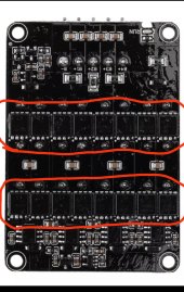
I did a quick Google and found for example this voltage comparator MAX9000ESA+
Here the datasheet http://www.maximintegrated.com/MAX9005.pdf
Could you kindly point out which value stands for the tolerance!? I can't find the word tolerance anywhere.

The kind Hankzor customer agent said the factory said there will be an extra cost of 0.5 to 1 USD. I suppose this refers probably to the more precise voltage comparators they will have to use!?
If you say too expensive, about what kind of amount are we talking? What is the price difference between 1% to 0.1% voltage comparators? Could the prices have dropped since last year?

Just for me to get an idea about what you said, ADC and more expensive systems, what do you mean with more expensive? Even more expensive than your KISS BMS or just more expensive than the standard active balancers? Do the chinese BMS's use ADCs or voltage comparators etc?
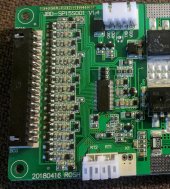
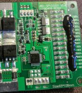
If i look at the cheap jbd smart BMS whose voltage readings pretty much match those of my 0.1% error voltmeter (resolution: 0.001V accuracy: ± (0.1% + 2digts) but no fluke though ;))

IMG_20220603_060351.jpg
IMG_20220603_060333.jpg
I can't see any of these same 8 legged voltage comparators like on the active balancer but many 3 legged voltage ref shunts. Is there also an ADC on the board, the big chip in the middle or do they use a cheaper method?
I have obviously no real clue but am someone who likes to get an idea/ understand the principle how something works.

Which modifications did you request/ tried to convey without success to heltec last year? Maybe helpful to convey those to the kind customer agent!? Or just let them do their thing first? I just ignorantly assumed that they simply need to change some resistors or so to raise the balance stop from 3v to 3.4v. maybe they install a potentiometer so we can adjust to whatever voltage we like?
Many thanks and best regards
Max
 
Last edited:
tossing in one more approach : microcontroller get cell voltages digitally from BMS UART (if it is available)

the JBD BMS (MOSFET type) i have has a UART serial data link, which can send all 4/8/16 cell voltages as well as estimated SOC. this should be able to get around the issue of low precision tolerance resistors etc. in the active balancer board.

then simple custom code to enable/disable the "RUN" relay.

the "benefit" of this theoretical approach is that completely custom logic can be switched out with ease, and hopefully the BMS will have more accurate voltage readings.

e.g.
Code:
if ( any cell voltage > 3.4 V )
{
  activateBalancer;
}
if ( SOC < 80% OR cannot talk to BMS )
{
  deactivateBalancer;
}
Hi curiouscarbon
Certainly another viable approach and probably especially interesting for those who are already versed in the UART Arduino r pi field.
In the past i followed here a thread of someone who successfully managed to build a small cheap module to send the jbd UART data via Arduino to the internet etc.. adding a cheap relay wouldn't be so hard indeed.
Best regards
 
Back
Top