diy solar

diy solar

Adding a second full rack of batteries to existing full rack

thanhrodke

New Member
Joined
Sep 8, 2022
Messages
131
Evening everyone,

I dug through search results, and saw lots of stuff related to adding one or more individual batteries, but nothing stood out about expanding an entire rack of batteries, so here's my first post asking a detailed question.

I've got another six EG4 LifePower4 48V lithium batteries (https://signaturesolar.com/eg4-lifepower4-lithium-battery-48v-100ah) and EG4 rack arriving this week. I'll be connecting them to an existing system that has six of the same battery, with the 12 batteries powering two EG4 6000EX-48HV 120/240V inverters (https://signaturesolar.com/eg4-6k-off-grid-inverter-6000ex-48hv). This is a 100% off grid system, with no option for grid input, though there will be generator power available (likely a 15kW propane Generac).

Each inverter currently has it's own 60V 200A Nadar breaker acting as the positive disconnect, with the positive cable from each of those breakers to top of the battery rack's left bus bar. The ground bar on the right is flipped and both inverters ground cable is connected to the bottom of the right inverted bus bar. Both cables are factory terminated 84" 1 gauge cables from signature solar.

When connecting the second battery bank, any issues with connecting it directly to these same points on the existing battery rack's bus bars? I'd flip the ground bus bar as on the first one, and using the same factory terminated 84" 1 gauge wire. Since there's no changes to the inverters, we don't have a current stacking issue like when wiring batteries in parallel. Total current running through the system will remain the same, as there are no changes to the inverters.

That said, there may be better alternatives, so please correct me if my logic above is not correct:
  1. Feed the breakers in parallel:
    Convert the lugs on the Nadar breakers to double mechanical lugs, and tie both battery racks to input side of the existing breakers. The inverters will still have a single 1 gauge cable from the output of the breaker to the input of the inverter. With a single breaker, I understand that I can't take one battery pack offline for maintenance.
  2. Individual breakers for all:
    Connect the new battery bank to it's own breakers, then up to the inverters (though not sure there's room to convert the inverter to double mechanical lugs). If this is recommended, what's the recommended method for connecting to the inverters? Is it to use bus bars after the breaker? This doesn't seem right, as it's not an inverter disconnect at this point, it's a battery disconnect. You'd have to flip two breaker (or maybe even four) to shut down one or more inverters, depending upon how parallel you went with the bus bars.
  3. Single breakers with bus bar before the breakers:
    Move to a bus bar setup (introduces at least some resistance and heat) where each battery connects to a bus bar, then a single output from the bus bar feeds a single breaker for each inverter input. In this case, how do you disconnect a given battery rack?
  4. Inline breakers between battery racks:
    Wired as originally proposed, but add breakers inline between the second battery rack and the first. This would allow the second battery pack to be taken offline and serviced, but not the first (by itself).
  5. Breakers everywhere:
    Use breakers as close to each battery rack as is feasible, then tie all of those battery banks to a common bus bar.
  6. Wire battery racks 1:1 with inverters:
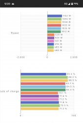
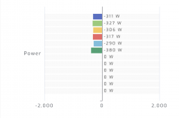
    I've watched the inverters closely the last few weeks, and think that they reasonably share the AC output load, so that even if the system were two battery/inverter systems running in parallel, both batteries will be charged and discharged pretty close to each other. Even if they different by a few percent, that's not the ideal scenario
  7. Wire battery racks 1:1 with inverters:
    Same at #6, but have a set of 1 gauge parallel cables between battery banks to keep them a little better balanced.
After typing all that out, it feels like there's certainly some magical combination of protection, useability, and serviceability.

Ultimately, this system will just have the two inverters and two battery banks. However, I will be building another system in a few months that will have four inverters and four racks of batteries with about 30kW of panels, so that's open for discussion here as well.
 
No one willing to take on the great wall of text? Lol

The second rack's bus bar is currently hooked up to the first rack's bus bar via the set of cables that come with the EG4 rack. They are 25mm^2 cables, which is a touch smaller than 3 gauge.

I folded the lugs over with pliers, then crushed them in a vice, then soldered them.

So far, not looking good. Not sure if it's the cables, my terminations, the smaller gauge, or the fact that I never balanced anything out (just hooked the second rack up), ut the first rack charges and discharges much faster than the second.

I've never had them both fully charged though. I assume that will happen sometime this week. Family has been doing lots of driving this weekend and charging the cars.
 
Last edited:
I didn't read all if it. I think you would benefit from watching a few YT videos from David Poz and Off Grid Garage. They have discussed battery connections quite a bit.
 
I have watched a large number of David's videos, even pre-beard. Enjoyed watching a number of the Off Grid Garage videos. Thanks for the recommendation on that.

From what I have seen, David has had a lot of discussion on current stacking in parallel banks as the cables get closer to the inverter, since those are carrying both the batteries nearest the inverter, and those further away in the parallel string. MY current configuration as described in post #2 fits this bill, and I am seeing way different charge and discharge rates between the two racks.

Off Grid Garage seems to be doing everything with individual cells, and running much less battery capacity than the two full racks that I have.

In my case, I have two full racks of six EG4 LifePower4 batteries each, and the question is the best way to tie those two together. Much of my extended discussion above includes serviceability of each bank individually, and if that has any merit.
 
Here's a couple of examples of the weirdness that I see in the charging and discharging:

In the first example, on the morning of the install, the first battery bank started in the low 50% range, and the second in the high 50% range and the first battery rack lapped the second one when charging. You can see how much more each battery in the first rack was taking.

In the second example, during a period of lower use, solar assistant recorded that only the first six batteries were discharging at all, with nothing reported from the second six.

I find the behavior pretty odd.
 

Attachments

  • Screenshot_20220925-122001.png
    Screenshot_20220925-122001.png
    86.5 KB · Views: 19
  • Screenshot_20220925-173043.png
    Screenshot_20220925-173043.png
    161.9 KB · Views: 19
Off Grid Garage seems to be doing everything with individual cells, and running much less battery capacity than the two full racks that I have.
He is currently running 2 each 14.3 kwh and 1 each 15.5 kwh batteries in parallel .
44.2 kwh with another 14.3 kwh pack sitting on the floor disconnected.


If I understand correctly, your first rack has 84 inch wires leading from that racks bus bar to the inverter and your second rack has its 84 in wire connected to the first racks bus bar. If this is correct, then you have 168 in of wire between the second rack and the inverter.
 
Last edited:
And without reading everything that you wrote in the first post, i think your wire is grossly undersized.
 
I think you are OK doing it as you have because each battery pack has it's own breaker too, as well as each inverter.
The batteries will take time to balance out overall.
I just connected a self made 14kWh, 11kWh and 4 Felicity 10kWh. They have charged each other, sucked from each other and taken a rest but are now all sitting around the same charge with all 96 cells at 3.34/3.35.
 
He is currently running 2 each 14.3 kwh and 1 each 15.5 kwh batteries in parallel .
44.2 kwh with another 14.3 kwh pack sitting on the floor disconnected.

If I understand correctly, your first rack has 84 inch wires leading from that racks bus bar to the inverter and your second rack has its 84 in wire connected to the first racks bus bar. If this is correct, then you have 168 in of wire between the second rack and the inverter.
I will continue to work my way through his videos, he's got a lot of content!

yes, other than I forgot that I had actually used both of the 84" 1 gauge cable sets from signature solar connecting the first pack to the inverters (one set each). The second rack is currently connected to the first rack with the ~3 gauge cables that came with the EG4 rack.

but unless I am at high load, those reasonably short distances should not come into play with as large a difference in charge and discharge rates as I am seeing. I see large differences even when the system is pulling under 50 amps from the batteries.
 
And without reading everything that you wrote in the first post, i think your wire is grossly undersized.
Agreed, the final system will have larger wires, and your line of discussion pushes me towards doing a large bus bar system.

That said, if the battery banks were in parallel, I think that each battery bank would only supply about 120 amps under full inverter load.
 
I will continue to work my way through his videos, he's got a lot of content!

yes, other than I forgot that I had actually used both of the 84" 1 gauge cable sets from signature solar connecting the first pack to the inverters (one set each). The second rack is currently connected to the first rack with the ~3 gauge cables that came with the EG4 rack.

but unless I am at high load, those reasonably short distances should not come into play with as large a difference in charge and discharge rates as I am seeing. I see large differences even when the system is pulling under 50 amps from the batteries.
Yeah, voltage drop.
Also, i edited previous post with a recent overview video link.
 
I think you are OK doing it as you have because each battery pack has it's own breaker too, as well as each inverter.
The batteries will take time to balance out overall.
I just connected a self made 14kWh, 11kWh and 4 Felicity 10kWh. They have charged each other, sucked from each other and taken a rest but are now all sitting around the same charge with all 96 cells at 3.34/3.35.
Patience definitely needed. I need to get all 12 batteries to a full state of charge and see how they behave after that.
 
This is the best method to keep everything shared equally.
is everyone's favorite bus bar pick the Victron? and if I have solar assistant connected to both inverters and all 12 batteries, is there any benefit to having the smart or modular bus bars?

next year, I'll be building another fully off grid system that will be twice this size (large house, tesla charging after 195 mile round trip work commute, lots of 3-5hp woodworking tools. that system will be four EG4 6000EX/6500EX inverters and 24 EG4 Lifepower4 batteries (120Ah) along with about 30kW of solar panels.

I only see a single Victron non-smart bus bar with eight high current connections, which would be needed for the four batteries and four inverters. I envision all eight connecting to that single bus bar. Is my thinking correct?
 
I am using these for my setup of 2 inverters and 6 batteries. The 4 Felicity 10kWh units are wired together with their own supplied cables then up to this bus bar where the other 2 batteries and inverters are connected. 250A busbar 5/16" studs
 
I only see a single Victron non-smart bus bar with eight high current connections, which would be needed for the four batteries and four inverters. I envision all eight connecting to that single bus bar. Is my thinking correct?

You can also stack lugs so you do not need 1 separate bolt per connection (many busbars specifically are approved for stacking). It's also even preferably to stack your highest 2 current connections on top of each other on same bolt so the those connections don't even need to go through the busbar itself. Otherwise you also put highest current connections near center of busbar.
 

You can also stack lugs so you do not need 1 separate bolt per connection (many busbars specifically are approved for stacking). It's also even preferably to stack your highest 2 current connections on top of each other on same bolt so the those connections don't even need to go through the busbar itself. Otherwise you also put highest current connections near center of busbar.
do the experts here like the blue sea stuff as well?
 
Back
Top