thanhrodke
New Member
- Joined
- Sep 8, 2022
- Messages
- 131
I did not, and don't know that I can even tell you what that procedure would be exactly. All 12 batteries have reached the 100%+ mark, and sat there for at least 12 hours.Did you ever do a slow top balance for both battery racks?
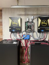
I ended up terminating the other set of ~3ga wires that comes with the EG4 rack, and using that in parallel with the first one. So the first rack is terminated to the inverters, and the second rack is cabled to the first rack with a pair of ~3ga cables.
They charge/discharge a little more evenly now, but at some point here before too long, I will order all matching cables, and convert the system to bus bars so that both racks and both inverters are in parallel.