diy solar

diy solar

Adding an ESS to Enphase Enlighten System

svetz

Works in theory! Practice? That's something else
Joined
Sep 20, 2019
Messages
7,297
Location
Key Largo
NOTE: This is a brainstorming discussion, nothing has been tested or proven to work.

This is essentially plugging a DIY battery into the Enlighten's generator port, there are some specific minimum sizing rules for that port, but nothing that looks insurmountable.

Note: The design in this post is constantly changing throughout the thread to improve and simplify it. It's just a starting point, if you just want the latest and don't care about the thought process that went from alpha to omega (if we ever get there) feel free to skip to the end.

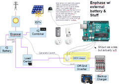
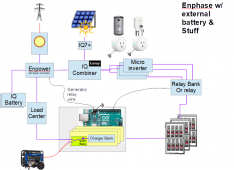
The big problem seems to be how to charge the system only when there's excess solar power. The system below uses a sensor to determine how much excess power there is and from that turns on/off a variable number of chargers.
1656854580750.png

The image shows cheap 15/20 amp wifi wall plugs, but large amp devices (e.g., hot water tank) will require something heftier. If it's a 10kWh battery, 2000 watts of chargers (4 chargers) should recharge it in ~5 hours assuming there's enough excess solar.

Charging priority (e.g., you need the EV charged more than the battery) could be switched on the fly via a cellphone app.

So, is there as simpler way? Anything plain stupid or problems you foresee? Any improvements you can suggest?
Seems like some sort of alarm is needed if the mcu hangs (less the battery drain via charging itself).
 
Last edited:
When does it activate the generator input port, and does it then sync to it and do generator support functions? I hope it knows not to ever back feed into a generator. I have the generator input to my XW connected to a port for my 5,000 watt gasoline generator. It knows to not back feed when on the AC2 generator input, but my Enphase inverters would not know about it, so I have to manually turn off the solar breaker before I use the generator input. That should be on an interlocked transfer switch.

I think it would only take that power in when there is a grid outage. I can see that working, but unless you have frequent outages, is it worth having that battery bank just sitting there? The logic looks sound. If there is extra solar, turn on a charger. This is very similar to the original idea I had for adding storage to my Enphase system, before I settled on the Schneider inverter. I almost bought a few cheap chargers and "grid tie" inverters from Ali Express. When there is extra solar, turn on a charger, or two, maybe 4. Then when the sun is going down, activate a grid tie inverter that would pull power from the battery and push it to my main panel. Mine would not have done backup power, it was to just time shift power to get around the time of use charges. I decided not to do it with the pile of Ali Express stuff when I thought about 4,000 watts of power being pumped around, and with the cost of the batteries, why have it controlled by cheap chargers and inverters, and still not have real backup power. So then I looked at off grid inverters and learned about AC coupling.

What is your goal for doing this? Is it to add more run time when the grid is down? That should certainly work. How is it going to compare to adding another Encharge-10 on cost and capability? A pair of the 5.1 KWH server rack batteries and something like a 6,000 watt Sigineer inverter charger could do the job.
 
Stuff in italics is cut/paste from the manual....
When does it activate the generator input port,
IQ System Controller takes care of turning on and controlling auto-start generators when the utility grid is down, without any intervention from homeowners. The generator reduces dependency on environment variables (irradiance for solar power production) and provides an additional power source while the system is off grid. The generator can be used to supply power to loads and/or charge batteries.

Eco-friendly: The generator is started and stopped automatically based on battery State of Charge (SOC).


and does it then sync to it
Enphase’s generator support solution is “Generator AND PV + storage,” meaning generator and renewables (PV and IQ Battery) can operate at the same time providing backup power for the homeowners seamlessly.

and do generator support functions?
The Enphase Installer App provides an user configurable Generator Exercise Mode option. For example, the generator runs for 15 mins occasionally to keep its engine in good operating condition, as required by the manufacturer.

The “Quiet Time” feature provides the user a way to select a period during which the generator stays off unless battery SOC drops below a critical charge threshold.

In the diagram in the OP I lose out on the support functions, possibly someone will have some ideas about that. For some, it might make more sense to feed the generator directly into the generator port via a manual transfer switch to swap between it and the off-grid inverter. Wouldn't need the backup charger that way.

I hope it knows not to ever back feed into a generator.
The IQ Gateway in the system measures the generator, the PV, and the battery storage outputs to avoid back feeding power from PV or storage systems to the generator

Which sounds great, but I suspect some of the "minimum" sizing is to make sure there's enough metal to absorb surges when the high amp devices shut off (e.g., AC going off).

I have the generator input to my XW connected to a port for my 5,000 watt gasoline generator. It knows to not back feed when on the AC2 generator input, but my Enphase inverters would not know about it, so I have to manually turn off the solar breaker before I use the generator input. That should be on an interlocked transfer switch.
In a normal system (not the above configuration) the inverter generator goes through the NFT, so pretty nice really.
In the system above, the generator is just to charge the auxiliary batteries.

... is it worth having that battery bank just sitting there? ...
Really great question!

Currently, I'm light on both kW & kWh when the sun isn't shining so have to hunker down using a small subset and careful management based on the day's solar input. Ideally, the extra battery would let me capture excess sunshine to reuse at night.

No natural gas here, so I have to truck fuel for the generator...not always possible when the roads are out (last big storm we had boats and trees blocking the highway afterwards ;-). We're lucky in that it only takes days for stuff to happen as engineers need to inspect bridges before work crews are allowed to use them. Not knocking them, those guys are truly amazing and heroes in my book. But, a lot of that happens as fast as it does as power & gas companies are incentivized (e.g., we're not buying their product), as those companies weaken I expect more and longer disruptions.

The other problem is the generator needs to be an inverter generator to feed into the Enpower, and the one I have isn't. The configuration above let's me use what I have.

Long term I need to get rid of the generator though. Currently, when I store fuel for it, at the end of the season I put the fuel into the car lest the fuel go bad. When I swap out the last gas vehicle for an EV, I won't have anything to do with the excess gas.

The logic looks sound.
Thanks for taking the time to go through it, always appreciate another pair of eyes.

What is your goal for doing this? Is it to add more run time when the grid is down?
Both energy (kWh) and power (kW). When the sun's not shining I've only a skimpy ~5 kW of inverter.

How is it going to compare to adding another Encharge-10 on cost and capability? A pair of the 5.1 KWH server rack batteries and something like a 6,000 watt Sigineer inverter charger could do the job.
Haven't compared costs yet, wanted to get the "alternative" down first so I could compare apples to apples.

Let's see, an IQ battery 10 is currently around $8k, has 10 kWh energy and 3.8kW inverter power.

The big costs in the system above appear to be the inverter and battery. At 30¢ Per Wh a 10 kWh battery is $3000. An 8kW Inverter (next size up on the minimum sizing for my current system) is about $4000, so $8k with all the other stuff?

Seems like a wash.... But, the more storage you want the cheaper it gets. For example, to add on an additional 10kWh would only be around +$3000. So $11k vs. $16k, or $14k vs $24k for 30 kWh. I'm certain battery prices will drop, but the kicker is if I'm going to DIY I should do it before Florida adopts NEC 2020.
 
I think the Schneider generator input would also be much happier with an inverter generator.

The one time I really needed my generator, the Schneider was not happy with it. The governor is not working right, and the rpm was bouncing too much. That caused the XW-Pro inverter to disconnect from it. It kept re-trying each time the load was removed the generator would get stable, so it would qualify as good, then try to connect again, the rpm would dip and overshoot, and disconnect again. The lifetime energy report in the Schneider says I got 5 watt hours from the generator. Yes just 5 watt, not kilowatt, hours. The funny thing is, I plugged my refrigerator directly into the generator, and it was able to stabilize and the fridge ran fine, taking that 250 wat load off of the XW and my battery. I then plugged my 600 watt charger into the generator, and connected it to the battery bank. Again, after a dip and rev, the generator took it just fine, and now I had net energy going into the battery bank, as the house was only using about 300 watts at the time when the power was out. So my big fuel big 5,000 watt generator was supplying less than 1,000 watts, but it was doing something. In just over 2 hours, my battery state went up almost 4% on the BMS. It was getting late, so I went back to everything absolutely necessary on the battery and shut the generator off for the night. I got the total load down to under 500 watts, hoping what I had left in the battery would get us through the night. The power came back on at 1 am. But had it stayed off, I was thinking about what I would have to do for a dark start if it had shut down.

There were two reasons I got into that situation. The big one was that I only had 18 KWH of battery, that I was only charging to 80%, and my system had just completed pushing almost 12 KWHs during the 4 to 9 peak time, so when the power went out, I was down to under 3 KWHs left in the battery. That was very dumb on my part. There were no fires going on, and the weather was clear, so I had no reason to think we might have a power outage, so I was playing the game to try and manually eliminate all peak rate charges, before I had the PLC working. After that, I decided to never take the battery below 50% (9 KWHs remaining) to be sure I could make it through a night during an outage. Since I doubled the battery to 36 KWHs, I now let it go to 40% or 14 KWH remaining.

I keep saying I will fix the governor on my old generator, but I just never seem to get around to it. I had to put a new carb on it a couple years ago, and the link to the throttle butterfly is different. By only adjusting the spring tension, I got it to hold a steady 61 Hz with about a 1,000 watt load on it, so I figured it was good enough, but it overshoots was too much when the load changes.

A while back I found a program someone did to have an Arduino microcontroller operate a RC servo to make a true digital PID loop generator governor. Of course, now that I am thinking about this again, I can't find the project page.

Here is one video of this idea where it does not work quite right.


I think he has it running a DC generator directly charging the battery.

This one is working much better, but I don't know what hardware/software it is using at all. It is just a short looping video of testing the electronic governor.


Let me know if you are curious, and I will post back what I find.
 
...Let me know if you are curious, and I will post back what I find.
Nah, appreciate it though. As I said previously one of my goals is to get rid of the generator. With any luck one of the breakthrough technologies will really break through in the next few years. Saw that graphene batteries (more like capacitors really) are available on the market now (about the same energy density as LFP (theoretical though is 1050 Wh/Kg which 4x LFP currently), no heating issues, charges 60x faster, and are 12x more expensive). LFP was 8x the price it is now a decade ago, so who knows in 10 years?
 
Last edited:
Ditch the Solar sensor
Figured out a way to ditch the solar sensor. This is important as the function to calculate "possible power" based on light levels is tricky with a cheap and poorly calibrated light sensor. Power output also changes with temperature, the seasons, time of day, and the efficiency of panels. That is, the formula for every system would be different.

Here's the idea... the amount of excess solar power equals the amount the IQ Batteries are charging. Using the API (or CTs if Enphase disabled it) the system could turn on a corresponding number of chargers for the auxiliary battery.

If the Enphase batteries are full and the auxiliary battery's SoC is low, the system would turn on a charger. Worse case (no excess solar) it would transfer energy from the Enphase battery to charge the auxiliary battery. As the transfer incurs losses you'd cap that at a high preset (e.g., 95% SoC on the IQ Batteries), you only need enough out of the IQ batteries to trigger the system to charge them with excess solar as that would fire up the loop in the paragraph above.

For those of you already under NEC2020, having a simpler one-box solution also means it's more likely that a 3rd party vendor might enter into competition. Well, the inverter and brain could be put in one box...might want to split the batteries into multiple plug-ins like those expandable/modular solar generators (e.g., the Bluetti, Inergy).
 
Last edited:
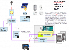
Once I put the inverter and chargers together in a single box noticed I could ditch the backup charger too!

1657057857825.png
The MCU could also forward maintenance generator start/stop to the real generator (it knows maintenance commands as they only come when the grid is live), which would allow the Enphase interface to be a one-stop interface...but, the MCU will have an interface for the precedence and overrides, so it could do that too.
 
Last edited:
Altered the image above so the "single box" would use an SPDT Relay rather than a wifi switch. Controlled by the MCU and ensures the generator and off-grid inverter phases can't intermix.
 
Last edited:
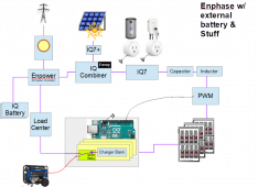
Wasn't crazy about needing such a big/expensive inverter, so took a look again at the prior PWM approach and came up with this:

1657107759799.png
This configuration operates roughly the same as the previous in terms of charging the additional battery. The inverter however is a smaller lower-cost grid-tied inverter powered by a battery rather than solar. The MCU would let the PWM bleed power into the IQ7s at a ratio of the total power to keep the SoCs of the two battery systems roughly equal so that both banks drained at about the same rate, this might be limited by the maximum C-Rate of the add-on battery. The inductor and capacitor are to smooth the choppiness of the PWM, they might not even be needed if the PWM frequency is high enough. If the IQ battery is not being drained and at a higher state of charge the PWM remains off. Similarly, if the IQ7s are off (e.g., anti-islanding), the PWM should remain off.

The downside is the ratio of IQ7s to IQ batteries. Due to the cost of the IQ battery most would already be at the limit of IQ7s meaning there's no headroom to add more. You could use IQ8s, but I've heard that requires a second Envoy (which seems odd) and costs ~$600; so it might not be cost-effective if you were looking to add a little power (kW) and a lot of energy (kWh).

Note that you can't use any old microinverter, this only works because the Enlighten system can throttle back the Enphase inverters. Anything else is probably going to need a full AC coupling solution to get the proper level of control and that will probably wreck the economics.

Costs - not worth it if you want the equivalent of adding an IQ10
An IQ10 is 10 kWh of energy and 3.8 kW power for about $8k. A matching system would be 12 IQ8s or $2.3k for the inverter part. At 30¢ Per Wh a 10 kWh battery is $3000, add in the Envoy and the balance of systems and the price is about a wash, so wouldn't be worth doing (especially with the complexity of control).

But let's say you only want to add 1 kW of power... 4 IQ7s would be just over a kW and cost $640. At 30¢ Per Wh a 10 kWh battery is $3000. The rest is probably under $500, so call it $4k, about half the cost of an IQ10. I can't add any more IQ7s, so let's use 4 IQ8s (1.2kW power) at a cost of $760, add in a second Envoy ($600) so that becomes $5k. If you wanted to add 20 kWh of energy and only 1 kW of power that's half the price of two IQ10 batteries, so there it does start to make sense.

Makes me wonder if Enphase will add battery extensions at some point. Makes sense since at some point you only need to add energy rather than power.
 
Last edited:
Just an FYI that Enphase's load controllers can be used instead of WiFi switches to eliminate any DIY programming to figure out the "excess" solar energy.

 
...I've heard that having both IQ7's & IQ8s requires a second Envoy (which seems odd) and costs ~$600...
Happened upon the reason while perusing the Enphase forums:
We cannot have both IQ7 and IQ8 microinverter series in one system as the firmware version used by both of them is different
 
Last edited:
That's odd, I thought Enphase was saying early on that iQ6 and 7 solar panel microinverters would work along with the iQ8's. When did this change? When I was looking into adding a few more panels, many places have no switched over and only carry iQ8's.

svetz... don't you have iQ7's on your solar panels with the iQ8's in the batteries? Do you have 2 Envoys?
 
... don't you have iQ7's on your solar panels with the iQ8's in the batteries? Do you have 2 Envoys?

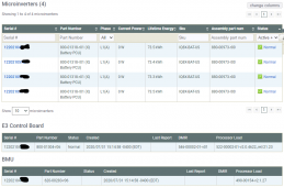
I only have one Envoy. I believe the difference is the "IQ Battery" has it's own control board that controls the IQ8s, that is they aren't handled by the Envoy like a sunlight system is. The IQ8s don't show up under the device tab nor are they listed with the inverters. Instead, the batteries are on the device list. The image below is a device drill-down into a single battery showing it is comprised of three component groupings. The IQ8s in the IQ Battery also have different part numbers than the rooftop ones (and probably not surprising they have different specs).

Possibly, at some point, they'll get the software down to a single load and the requirement for multiple Envoys will go away
 

Attachments

  • 1657383563919.png
    1657383563919.png
    86.2 KB · Views: 10
From watching @ncsolarelectric electric's experiments, it occurred to me that the output from a single microinverter isn't that much and we could reuse the prior technique of incremental charging.

As microinverters are current sources, when connected to a battery they output their continuous maximum power. In the diagram below, a relay is used to power individual microinverters, so if you had 300W microinverters and needed 800W, you'd turn on 3 relays providing 900W. Enphase would then throttle other inverters back to reduce the energy by 100W.

If the microinverters could be throttled and controlled by Enphase (e.g., IQ7s or IQ8s) you'd only need a single relay rather than a bank of them. Unfortunately, the Enphase system would prioritize the battery-powered microinverters over other non-solar energy sources, so even though they could be throttled to zero output you'd still want at least one relay to only output power when you wanted to.

1659368456408.png

A lot of the back-feeding issues around the system are due to the rooftop microinverters' speed of throttling during a surge event; but if the backup is only activated during the night then there is no power coming from the rooftop solar microinverters.

Finally, for systems where the number of IQ7 microinverters is limited due to the engineering requirements for the IQ battery, then in the drawing above for nighttime use that limit can be bypassed by PV Shedding panels that aren't producing because it's nighttime. No physical changes need to be made for this. If using IQ7s and otherwise meeting the IQ Battery guidelines, this layout should be surge-safe.
 
Last edited:
I am a bit leery about the idea of connecting a battery to an MPPT input. Solar panels always drop in voltage as the current increases, and at some point, the voltage drops enough that the wattage falls. But with a stiff battery, an MPPT may keep seeing the power rise as it increases current. If it is "smart" enough, it should limit when it pulls it's rated power, but many are not that smart. While the Enphase iQ7 might be smart enough, I don't know if I would want to push that all the time.

As for shedding PV power during the day, I was thinking of having a relay switch in a resistor between the solar panel and the iQ7 inverter. It would look like a cloud moved in and drop the power a lot, but it would keep operating and be able to turn back on instantly, no 5 minute qualifying on the grid side.
 
Interesting discussion. I had thought about doing something similar (albeit without the Enpower). I think you are going to have to cut off the AC side of the microinverters rather than the DC side, but I forget why I came to that conclusion in my original analysis. I also think there is a bit of room for simplification still. One thing I would be concerned with is the phase balancing of the chargers. I think you need to have the load split between phases on the utility side, and then single-phased on the generator side (assuming you are using a 120V generator).

One product I would recommend taking a look at is the ShellyPro series (specifically the Pro4). The ability to have logic, input, and output integrated simplified a bunch of things in my concept. Most of the programming in my scenario would just be done on the Shelly.
 
In looking at the diagram above, the generator could be moved to the Enpower; the advantage mainly for big generators in that they could both recharge batteries and power the home.

...with a stiff battery, an MPPT may keep seeing the power rise as it increases current. If it is "smart" enough, it should limit when it pulls it's rated power, but many are not that smart.

;) What happened to:
Over paneling on current will not hurt an Enphase inverter....

Here's my thinking, Microinverters have voltage limits that "set" the current limit, that voltage is the driver deciding how much current will flow through the circuit given Ohm's law (V/R=I). The minimum R from the MPPT is Rmin, so Vmax / Rmin = Imax and Vmax * Imax = Wmax; that is microinverters have to clip beyond Wmax if the voltage isn't exceeded.

While the Enphase iQ7 might be smart enough, I don't know if I would want to push that all the time.
This is an advantage the PWM approach has, the power can quickly and easily be tuned and the MPPT will treat it as a cloud effect.

Like a lot of inverters, the IQ7 has a continuous rating of 290W and a peak rating of 295W. Yet it's rated for 440W panels. It's a guess, but suspect it self-throttles based on temperature. Even so, you'd probably want to experiment with the input voltage to determine the continuous without overheating and pick a microinverter rated for high overpaneling.

As for shedding PV power during the day, I was thinking of having a relay switch in a resistor between the solar panel and the iQ7 inverter. It would look like a cloud moved in and drop the power a lot, but it would keep operating and be able to turn back on instantly, no 5 minute qualifying on the grid side.
Interesting idea!

I think you are going to have to cut off the AC side of the microinverters rather than the DC side, but I forget
Varying the DC side shouldn't be any different than time of day or cloud effects, but if you remember the issue please post it!

...One thing I would be concerned with is the phase balancing of the chargers. I think you need to have the load split between phases on the utility side, and then single-phased on the generator side (assuming you are using a 120V generator).
I was assuming a 240V generator and cheap 120V chargers, so you're right about the balancing. The fix would be to arrange the chargers symmetrically on L1/2 and turn them on/off at the same time while on the generator. When the chargers are powered by solar, it might not be as important as the Enphase NFT would compensate a great deal.

One product I would recommend taking a look at is the ShellyPro series (specifically the Pro4). The ability to have logic, input, and output integrated simplified a bunch of things in my concept. Most of the programming in my scenario would just be done on the Shelly.
Just to key off that thought, some IoT switches are only cloud-based; when you want them to work automatically is when the grid's out and the internet might be wonky, so they'd need to have local accessibility and a reliable/simple API, preferably with a query for their state.
 
... I also think there is a bit of room for simplification still...
Hope so, the numbers still don't look that good really unless you want a lot of energy. Adding on an IQ10 is ~$8k and brings 10 kWh energy with 3.8 kW power.

Let's say we can get working iQ7+s off eBay for $60/ea, then a roughly equivalent buildout with 12x 300W inverters and 4x400W chargers would be:

$720 - 12x iQ7+ @ $60 from eBay used
$ 10 - NodeMcu
$ 16 - 16-Channel Relay, 2 kW/channel
$280 - 4x 400W chargers
$3000 = At 30¢ Per Wh a 10 kWh battery is $3000, if you go cells and your own BMS 20¢/Wh + 55 - BMS = ~2100.
======
~$4,000 (or $3,000 with DIY cells)
+ 20% for breakers, wifi switches, wire
======
~$5,000

For $3k more you get monitoring compatible with what you have, guaranteed it'll work, support, and a warranty. The real cost benefit is when you want a lot more energy than a single IQ10 and don't need more power. For example, adding 30 kWh of energy with IQ10s would be $24k, but just adding +20 kWh to the system above only adds $6k, or $11k total. Guess that's not quite correct, you'd probably want to triple the charging.
 
;) What happened to:

Here's my thinking, Microinverters have voltage limits that "set" the current limit, that voltage is the driver deciding how much current will flow through the circuit given Ohm's law (V/R=I). The minimum R from the MPPT is Rmin, so Vmax / Rmin = Imax and Vmax * Imax = Wmax; that is microinverters have to clip beyond Wmax if the voltage isn't exceeded.
Over paneling still has a limit in the Enphase manual. And even paralleling four 300 watt panels for 1,200 watts in, it is still going to have far more series resistance than a lithium battery bank. Even a small increase in the pulse width could make a fairly large increase in current when the voltage coming in does not drop at all from the battery. For the first experiments, I would certainly fuse the connection between the battery and the iQ7 at about 10 amps. My iQ7 60-2 inverters are rated for 240 watts continuous from 60 cell panels. My 300 watt panels are about 40.53 volts open circuit, and 9.76 amps short circuit. That looks like 4.15 ohms of series R in perfect light conditions, and as less light hits, that resistance climbs fast. It is not a simple linear resistance like that, but it gives us an idea what the MPPT is looking at. We have to assume the MPPT seek uses fairly small steps. If the steps are small enough, it will be okay. It sees under 240 watts, it tries a little more current at the input, power goes over 240 watts, it backs off the current. It should all be good. But with such small series R from a battery, if the current step is a little too big, could it pull too much current before it is able to back off?

I agree it should be able to do this and limit at the 240 watt rating (295 for the iQ7A). But the fact they do list a maximum panel power limit makes me think there is a chance it could spike the current. If it was able to always safely limit the input current, then there should not be a maximum solar panel power limit. Obviously, if it does blow up, there won't be any warranty coverage. It might be as silly as an input fuse cast inside that solid housing. The current spikes up and the fuse goes pop, and the iQ7 is now a door stop.
 
Back
Top