We have 2 Sunny Boy 6000 String inverters and want to add a new separate string of 5 Solar panels with Enphase IQ8 micro inverters tied to a new Enphase IQ combiner. Can I connect the output of the combiner to the output of one of the Sunny Boy inverters?
You are using an out of date browser. It may not display this or other websites correctly.
You should upgrade or use an alternative browser.
You should upgrade or use an alternative browser.
Adding New Solar String to old system ?
- Thread starter SunnyMan
- Start date
Hedges
I See Electromagnetic Fields!
- Joined
- Mar 28, 2020
- Messages
- 20,624
You can have any kind of GT PV inverter with their AC outputs all landing on your grid-connected panel (within NEC amperage ratings for PV breakers backfeeding the panel.) They won't even be aware of each other.
If you may want to add battery backup in the future, it is good to use GT PV inverters which interact with it. Probably anything with UL-1741-SA frequency-watts would work.
If you may want to add battery backup in the future, it is good to use GT PV inverters which interact with it. Probably anything with UL-1741-SA frequency-watts would work.
Hedges
I See Electromagnetic Fields!
- Joined
- Mar 28, 2020
- Messages
- 20,624
Do you have multiple orientations where panels can be placed?
You might be able to "over-panel" the Sunny Boys without losing production due to clipping. All strings into an MPPT need to be similar Vmp, but can be different current and different orientation.
You might be able to "over-panel" the Sunny Boys without losing production due to clipping. All strings into an MPPT need to be similar Vmp, but can be different current and different orientation.
Ampster
Renewable Energy Hobbyist
The output of the micros needs to go through a circuit breaker. If that breaker is on the same sub panel as one of the Sunny Boys then they both will be in parallel and theoretically connected to each other through the bus bar. Even if they were fed through separate sub panels they would be connected in parallel through the bus bar of the main service panel. They will all synchronize to the grid. There are some code issues about how much generation can backfeed a bus bar but 5 Enphase inverters would not be significant. @Hedges said the same thing.Can I connect the output of the combiner to the output of one of the Sunny Boy inverters?
What are you trying to accomplish besides increasing GT capacity?
Last edited:
Hey, thanks for your answer. I'm a rookie here. I took some pictures, I'm thinking I could just get another breaker and install it on the A/C disconnect? (btw we have a whole house generator, so we wont need batteries). We have a 15wk system, but I checked our last bill and wondering why we are paying so much more. we are using 17.1 kw now. The original system was installed 8yrs ago.
Attachments
Ampster
Renewable Energy Hobbyist
Adding micros to a system with string inverters is a great way to increase capacity. You can orient the panels in different directions to spread out your generation so as not to exceed any limit in your interconnection agreement. Some utilities allow a 1000 Watt increase without needing a new NEM agreement.
Hedges
I See Electromagnetic Fields!
- Joined
- Mar 28, 2020
- Messages
- 20,624
35 + 35 + 20 = 90A of breakers in a 100A panel.
The 35A breakers would be your Sunny Boys. What is the 20A?
A panel normally is allowed to have PV breakers + main breaker no more than 120% of busbar rating, with PV at far end of busbar.
presume this panel protected by a 100A breaker elsewhere.
I think these panels have one busbar fed at each end, so there is no "far end".
I think a "PV aggregator" panel (no loads) is allowed to have PV breakers and main breaker each be 100% of busbar rating (don't recall exact code wording.)
So I see some difficulty making the system meet code fully. Maybe the 20A breaker is a convenience outlet for maintenance? Technically would make breaker panel not "aggregator" but wouldn't worry me personally.
Since this is ground mount, can you add new panels with a different orientation? After considering exact PV array series/parallel configuration and PV panel specifications, I might be able to figure out over-paneling to increase kWh/day from existing inverters.
Generator - does that just support loads, but inverters do not try to backfeed it?
Battery backup is nice even with generator - reduces run time. If interactive with GT PV, you get to use solar too, even less generator running.
Ampster
Renewable Energy Hobbyist
I do not know the capacity of the micros you are adding but it is unlikely that it exceeds 10 Amps so you may be able to put the micros on a 15 Amp breaker. That may help the calculation of the bus bar backfeed rule. Actually there are several rules and I am not well versed enough to give you specific advice. I understand them conceptually enough to know there are work arounds by derating a sub panel breaker. Another workaround may involve locating the micro breaker at a different sub panel or on the main panel.
I appreciate the help. We do have outlets hooked up to each inverter (we never use them, prob gonna remove them - see pic) and I did shut off the 20a breaker and the sunpower monitoring box shut off (see pic).
The Enphase combiner does have its own set of breakers.
Maybe I could just add the new 5 to the existing array string, just evenly distribute them? The spec sheet for each sunny boy 6000 says max system voltage per inverter is 600V , Max dc operating power is 6300kw, max input current 30a & A/C side: rated power 6k, max apparent power 6100va, Nom a/c current 25A, mac output current 25.2A. We have 33 - 345w sunpower panels (8yrs old) and 3 generic panels at 280W for 36 panels total and want to add 5 more.
Which way should we go?
Attachments
Ampster
Renewable Energy Hobbyist
That is an alternative and it involves string calculations which may be available in the Sunny Boy inverter manual or website. Matching solar panel specs may be a bigger challenge than the NEC bus bar rules?Maybe I could just add the new 5 to the existing array string, just evenly distribute them?
Hedges
I See Electromagnetic Fields!
- Joined
- Mar 28, 2020
- Messages
- 20,624
Most important is knowing how to calculate Voc at record coldest temperature. That is to avoid killing inverter.
With 33x 345W panels, 11385W STC, (PTC maybe 15% lower), the two 6kW inverters aren't fully loaded.
You could probably move more panels to one inverter, fully loading it. That would leave fewer panels on second inverter, and you just need enough new panels to make an equal voltage string.
See what you can work out, then post your proposed panel string arrangement along with links to data sheet of all panels and inverters so we can review it.
Hi Hedges, tx,
Here is the link to the Sunny Boy 6000 inverters: https://ressupply.com/documents/sma/3000-7700TL-US-22_Installation_Manual.pdf
The Sunpower panel data sheet: https://us.sunpower.com/sites/defau...1-series-335-345-residential-solar-panels.pdf
We also have 3 Solarworld panels (which a friend gave us) and looks like their website doesnt work: https://en.wikipedia.org/wiki/SolarWorld but can we assume they put out 225w each.
Currently total 36 panels. Here is todays (sunny blue sky's) reading. as you can see I hooked up the additional 3 solarworld panels to one inverter. Maybe we can hook up additional panels to the other inverter? if so how many could we?
Attachments
Hedges
I See Electromagnetic Fields!
- Joined
- Mar 28, 2020
- Messages
- 20,624
Assuming your location's record cold temperature is -15C, 40 degrees lower than +25C nominal, I calculate 6.696V increase in Voc, to 74.896V.
Series string of 8 panels maximum.
6000W/345W (STC) = 17 panels
Two strings of 8 almost fully load inverter, but only at "STC" output. "PTC" will be 10% to 20% lower.
I would like to put 3 strings of 8 on the inverter, 8s2p into one MPPT and 8s into the other, with some of the strings oriented different from the other, e.g. 8s aimed SE and 8s2p aimed SW. That should never clip.
That leaves just 8s for the other inverter (and one spare panel.)
Now all you need to do is gather other model panels totaling about 460 Vmp per string and < 600Voc (adjusted for cold.)
If you shop around you could find other SunPower panels. Or you can mix brands.
The newer SunPower panels claim "PID free", other brands vary in how they are affected.
Your -22 inverters are transformerless, ungrounded PV array, so half the panels are biased above ground, half below ground.
Panels which are affected by PID prefer to be biased one way only, to avoid that. Early SunPower panels had a problem with negative ground, positive bias (which was typical for other products.) They improved newer models.
I'm using transformer type, and I positive ground my SunPower, negative ground the others.
Thanks for the expertise (without paying a solar company to have a site visit and charge us).
Since we are only a "little" bit savvy, in lemans terms: Can we just add 3 - 370w LG panels (1110w) to the 2nd inverter?
Current:
1st inverter: 17 x 345w panels 5865w + 3 x 225w panels = 6535W
2nd inverter: 17 x 345w panels 5865w
Proposed:
1st inverter: 17 x 345w panels 5865w + 3 x 225w panels = 6535W
2nd inverter: 17 x 345w panels 5865w + 3 x 370w panels (1110W) = 6975W <<<????
TX
Hedges
I See Electromagnetic Fields!
- Joined
- Mar 28, 2020
- Messages
- 20,624
Sunny Boy 6000-TL-US-22 has:
2 MPPT inputs, 15A max operation, rated 210 to 480V operation.
You can parallel 2 strings on one MPPT, but they need to be same/similar Vmp
2nd inverter, instead of 17 panels, I think 8s2p 345W for 458V, 12A, 5520W on one input
3s 370W on second MPPT input (what is Vmp of this panel? probably too low to reach 210V, so won't work.)
Need to see exact specs of 370W panel to consider alternatives. Might use in series with several SunPower, in which case you get the lower current of the two. Might put in series with the 225W panels, need their specs.
Similar issues for 1st inverter.
I'd try to make some strings 100% SunPower, see if 3s 370W connected in series with 3s 225W can make one string (based on PV panel specs.)
Panels, especially used panels, are relatively cheap, e.g. a pallet of them shipped from SanTan Solar. You could buy enough of one model to make a suitable string, maybe 2500W for $600 to $1200, plus shipping (can be $200 +/- depending on your location.) Not all brands are quality, there are reports on various degradation mechanisms.
Hedges
I See Electromagnetic Fields!
- Joined
- Mar 28, 2020
- Messages
- 20,624
PV wires between Sunny Boy TL-US-22 and disconnect switch?
I just picked up one of these inverters, and it came without disconnect switch. At least initially I plan to use a DC switch I already have; it if works then maybe I buy one.
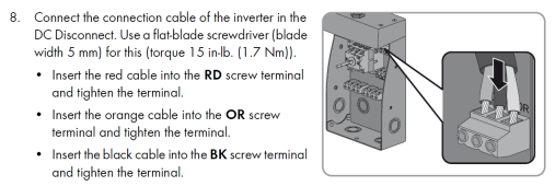
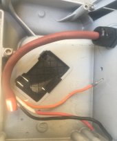
There are three wires, Red, Black, Orange. Instructions simply call for connecting them to corresponding terminals of switch.
I expect PV+, PV-, possibly ground. Can you tell me what he three wires are?
It came with RS-485 module, also SPS, but is missing the small ribbon cable to connect SPS.
I'm going to see if 120V operation is supported, maybe use this for a 120V only single Sunny Island system.
SPS could be convenient for black start, jump-start itself if batteries get run flat.
Thanks!

Ampster
Renewable Energy Hobbyist
I would not want to switch the ground.I expect PV+, PV-, possibly ground.
Hedges
I See Electromagnetic Fields!
- Joined
- Mar 28, 2020
- Messages
- 20,624
True, not switching ground. But of three wires from switchbox to inverter, ground could be one.
Alternatively, there is a toothed washer where socket head cap screw mechanically holds switchbox to inverter. But I'd rather only depend on those to ground incidental metal objects, like a cover. Not to complete the intentional fault-clearing (or safety ground) path between inverter and array.
With diode check and capacitor scales I think I've confirmed Red is PV+ and Black is PV-. But Orange has funny connections to red and black, also shows diode and capacitance.
For now, I've capped Orange, connected Red and Black to MC3 pigtails so they diode-check same as my "new" SB -41.
Orange is same gauge as Red and Black. Don't know what function would require 3rd wire for non-isolated PV array, except safety ground.
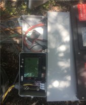
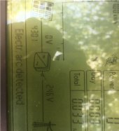
With AC connected to 120/240V split-phase + ground (twist-loc extension cord), DC connected to PV+/PV- + ground (UF & safety switch), I turned on AC first, DC second. Display says, "Electric Arc Detected" "Check DC Generator" "Please confirm by tapping"
So I knocked and I knocked, but no body home.
RTFM:
"8206
Electr. arc detected
Please confirm by tapping The inverter has detected an electric arc and was recommissioned after a disconnection. By tapping, you are confirming that you have repaired any possible damage to PV modules, cables or plugs in the PV system.
Corrective measures: •Tap on the display within ten seconds of the display message appearing in order to recommission the inverter."
So I gotta go back and cycle power, work faster this time.
Alternatively, there is a toothed washer where socket head cap screw mechanically holds switchbox to inverter. But I'd rather only depend on those to ground incidental metal objects, like a cover. Not to complete the intentional fault-clearing (or safety ground) path between inverter and array.
With diode check and capacitor scales I think I've confirmed Red is PV+ and Black is PV-. But Orange has funny connections to red and black, also shows diode and capacitance.
For now, I've capped Orange, connected Red and Black to MC3 pigtails so they diode-check same as my "new" SB -41.
Orange is same gauge as Red and Black. Don't know what function would require 3rd wire for non-isolated PV array, except safety ground.

With AC connected to 120/240V split-phase + ground (twist-loc extension cord), DC connected to PV+/PV- + ground (UF & safety switch), I turned on AC first, DC second. Display says, "Electric Arc Detected" "Check DC Generator" "Please confirm by tapping"
So I knocked and I knocked, but no body home.
RTFM:
"8206
Electr. arc detected
Please confirm by tapping The inverter has detected an electric arc and was recommissioned after a disconnection. By tapping, you are confirming that you have repaired any possible damage to PV modules, cables or plugs in the PV system.
Corrective measures: •Tap on the display within ten seconds of the display message appearing in order to recommission the inverter."
So I gotta go back and cycle power, work faster this time.


Hedges
I See Electromagnetic Fields!
- Joined
- Mar 28, 2020
- Messages
- 20,624
This time I knocked as soon as message about arc was shown, and it sequenced through relays then connected and started producing power.
1400W with one 2500W string (off angle at this time.)
Now I'll shop for a matching disconnect switch. And SPS ribbon cable.
Not bad "For parts or not working" (and priced appropriately)! I'm running 2 for 2 so far.
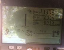
1400W with one 2500W string (off angle at this time.)
Now I'll shop for a matching disconnect switch. And SPS ribbon cable.
Not bad "For parts or not working" (and priced appropriately)! I'm running 2 for 2 so far.

Hedges
I See Electromagnetic Fields!
- Joined
- Mar 28, 2020
- Messages
- 20,624
Looks like Orange and Red are separate PV+ inputs for two MPPT. Black is shared PV-
"DC Input
Maximum DC operating power 8,000 W
Maximum system voltage 600 V
Rated MPP tracking voltage range at 208 V AC 230 V to 480 V
Rated MPP tracking voltage range at 240 V AC 270 V to 480 V
Rated operating voltage 400 V
Minimum operating voltage 125 V
Start voltage, no-load status 150 V
Maximum input current 30 A
Maximum input current per MPP tracking input 18 A
Maximum short-circuit current per MPP tracking input 19 A
MPP tracking inputs 2
Strings per MPP tracking input 2"
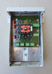

Similar threads
- Replies
- 8
- Views
- 304
- Replies
- 1
- Views
- 104
- Replies
- 3
- Views
- 275
- Replies
- 3
- Views
- 193


![20220207_111449[1].jpg](/data/attachments/82/82793-195cbffd2635904a7b2c19dae98a5cb4.jpg)
![20220207_111426[1].jpg](/data/attachments/82/82794-60b6cf6c347f304b0e2944c835a5f02e.jpg)
![20220207_111526[1].jpg](/data/attachments/82/82795-cefc6f12c2188b84c0c9abc7a5e0d13f.jpg)
![20220207_120057[1].jpg](/data/attachments/82/82801-79ab79a857c990c74f44e04dc4751638.jpg)
![20220207_120103[1].jpg](/data/attachments/82/82802-5fd4226697d1e477a18b5d5ab082cd46.jpg)
![20220209_100337[1].jpg](/data/attachments/83/83081-f5e02de0118053a597b58494d84e6156.jpg)
![20220209_100342[1].jpg](/data/attachments/83/83082-230548e5838c941f2d0af614a49a7e4b.jpg)