diy solar

diy solar

Adding Schneider XW Pro

The system isn't pressurized. But the chiller is the first thing after the pump depending on the the internal flow restriction it could be up to 10 psi at that connection.

I'm sure if I put it together as is, there will be no leaks.
My concern is the hot/cold cycles allowing the hose and clamp to slip off over time.
I don't trust a hose clamp on a smooth surface long term.
That's why any connections held together with a clamp will have some sort of mechanical feature preventing the clamp from sliding off.
 
I would be willing to try and machine a part for you on my lathe. My only real concern is I like to have the part I am mating with so I can measure with the same tool and test fit the part. My Harbor Freight digital caliper is nice, but will it be within 0.002 inch with your measurement of the boss up there? If you do use a gap filling epoxy, I guess a 0.005 clearance fit would be fine. What size pipe fitting thread are you looking for?
 
Good point. I just tried and couldn't even get a good reliable reading on the lower port, due to everything else nearby.

Loctite 680 shows a maximum clearance of 0.015"

I think I'll probably just order a 12mm drill bit and do it with epoxy.
 
I know your battery cabinet is out in the sun, but how hot is it really getting? How much current are you running in and out of the batteries? Mine do not seem to be making any heat at all. How much power is the chiller going to need?

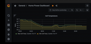
It was a little cooler here today, we got down into the 50's overnight, and just hit low 90's for the high. My battery temp never got over 23C or just 73.4 F as the outside air hit 90, and it was about 82 or so in my garage where my batteries are. With the second pack connected (a total of 4 x 3P strings now) my maximum current per string is under 25 amps discharging. And charging is way less than that now at less than 11 amps per string, even with the worst case imbalance I have seen.


I don't mean to hijack your thread, but I figured you would find this interesting...

I did a little test of the voltage drops under current today. The new battery bank is showing about 20% less series resistance. It appears most of the is the BMS, but some must also be in the actual cells. My old pack is sharing the single 200 amp rated JK-BMS which is measuring about dead on 0.001 ohm or 1 milliohm. In the new pack, each of the two 3P strings has it's own 100 amp rated Daly BMS. While each one is measuring about 1.2 to 1.3 milli Ohms ( about 0.00125 ohms), the two in parallel are measuring less drop than the JK-BMS, and calculating out to just 0.0006 ohms (0.6 milli Ohms). The total cable and fuses etc. are all about the same as the original pack, but it does also have two shut off switches in parallel, so that may also reduce the voltage drop a little as well. As the system has been cycling for 3 days now, the new pack is pulling a little more current in both directions, so it is not a balance issue. Th new pack has a little more capacity, and a little less series resistance.

Admittedly, my clamp on amp meter is not the most accurate at lower currents, but I repeated th measurements, and even flipped the jaw around to read them as negative current as well to reduce any offset effects. At a 27 amp total charge current, the old battery bank was only taking 12 amps, while the new battery bank was taking 15 amps. The is a significant difference. At that moment, the new battery bank was puling 25% more of the current than the old battery bank. WOW! With the longer cable run, I really expected the new pack to take less of the power. I wonder how much of this is the fact that the new bank maybe has 5 cycles, while my old pack has over 300 40%-50% cycles? The old cells are LG Vista 2.1 and the new ones are LG GEN 2.2 and they are 1/16th of an inch longer. I have commented on a few threads about parallel operation of non matching batteries. I knew the different version and age would cause a little imbalance in the current, but this is a bit more than I was expecting. It will not cause any problem in my system. My voltage and state of charge range is well within the safe area, and even just a single string (I have 4 now) can actually handle the maximum current I am running, for both charge and discharge. So there is not worry about over stressing any of the cells.

At my new lower charge cutoff, the JK-BMS reported the cells only charged to 87% which does sound about right for 4.05 volts per cell. The inverter just cut off at my new raised lower limit of 53 volts (3.786 volts per cell) and the JK-BMS is showing that as 74% remaining, so I only pulled 13% out of the old battery bank. That is a small cycle. It shows the pack still having 267 amp hours remaining, and the numbers work out correct. The battery bank charged for 6 hours and 6 minutes, or 6.1 hours, at 27 amps. That works out to 164.7 amp hours. Only 46.8 amp hours came out of the old battery, so the new one supplied 117.9 amp hours. The new pack took 72% of the energy?? Wow. That is certainly way more off balance than I was expecting. I will have to track a few more cycles. It is not helping that the new Daly BMS units don't have any smart monitoring, so I am having to use the data from the Schneider XW-Pro and just subtract out what the old battery is doing. I think the Schneider may be over reporting a little. But I doubt it could even be 5% too high. So I really do believe my new battery bank is taking close to 70% of the energy transfer. And the new cells also seem to have a more efficient charge/discharge efficiency. I am getting more of the amps hours that I put in, back out. The old bank may also be doing better, since the current is now less than half what it was.
 
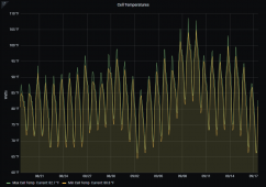
I've got more to share as I finish reading your post (after work this evening). But, while I have the PC up, I wanted to attach the last month of min and max temps.

1631911866156.png
 
So that is your battery cell temp sensors? Most days do not look too bad, but four days going above 100F is a bit warm. The battery temp sensor in my XW-Pro is not working. I can see it in the status screen, but it is not reported on any of the graphs. Current temp shows 84.74F, but when I go to the graphs, it shows a constant -278 degrees. I think they fixed this is the 1.11 or 1.12 firmware, I am still on 1.08
 
Yes, those are battery temperatures from my BMS. I do have the XW temp sensor connected. I verified it works (I believe it has 1.11?)

My BMS has 3 temperature sensors per string. So 6 in total right now. The graph above just shows min and max.

The vast majority of the temp raise is just ambient temp heat load.
I had one day where it didn't charge and the cell temperature raise was similar to the day before and after.
 
I just read through your post. Thanks for posting your experience connecting the new cells.

I am amazed at the current difference between new and old. That old pack isn't even that "old"
I think that your daily cycling might be something like 30,000 miles? There are Bolts at 100,000 miles with no reported/noticeable degradation. And your current is so low, those would be 30,000 easy miles.
 
My "old" pack has been online 1 year and 70 days. The BMS reports that I have cycled 27,000 amp hours in and back out again. The BMS divides that by the 360 amp hour battery capacity, so it says I have completed 75 cycles. It has actually been more like 350 cycles, but each one has ben about 40% of capacity. Now the normal daily cycles will only be about 25% of battery capacity. I didn't really need the second pack, but I am looking at extending the life, and also have more backup time when the grid fails.

To figure out how hard I am working the cells, I decide to try a little math on the number. A good efficient electric car can travel about 3.5 miles on each kilowatt hour. In one year, my small 18 KWH battery pack cycled enough energy to have pushed a car 27,000 amp hours x 55 average volts = 1,485 KWHs x 3.5 Miles per KWH = just 5,197.5 miles. Yes, I am being very light on these cells. Now this is only 3 of the 10 modules used in a Chevy Bolt, so, it we cycled the entire pack of a Bolt this amount, it would have travelled just shy of 18,000 miles. But that is a year and 70 days, about 1.2 years, so a year would be 15,000 miles. So yeah, I am actually pushing each cell about the same as an average higher mileage driver. It is about 40 to 50 miles a day. I put 20,000 miles a year on my Ford C-Max hybrid. Now with the doubled battery bank, I do see the cells lasting past 10 years at this cycle rate.

Once I add the DC charge controller and 9 more 300 watt panels, I might work the batteries a bit harder. At the same 5.2 "sun hours" as my existing panels are getting, 9 more on a DC charge controller would be pushing around 14 KWHs into the battery bank each day to use all at night. And that number is the power with my panels getting very hot, and they are dirty, and that is calculated off the power out of the iQ7 inverters, so I may even do a little better. And in the hot summer, with the panels flatter, they actually will get more sun hours. I will lose a bit in winter, but I don't need near as much evening power in the winter.
 
It's only 80f today, so not a great day for a test. But here I am ?‍♂️

With the pack at an average of 78f and ambient of 80f, the chiller is using 1.36 amps at 51.2 volts
70 watts at a roughly 2:1 COP should give me roughly 140 watts of cooling.

I've got to figure out how to measure compressor speed. I'm not sure of the current speed, but I know it can go faster.

The two 48 volt 120mm fans are the loudest part by far. It's nice and quiet overall.
 
Ok, well making a guess knowing the controller has a range of 3,000 - 6,000 rpm

The motor drive read 280hz, I adjusted the speed until the frequency stopped raising. Got 540hz max.
3.27 amps at max speed.
 
Um, thanks?

That was about the last response I expected and also the perfect response, well done!

Considering it's the end of September I probably won't have any real results until next summer. Perfect timing, as usual.
 
I got "lucky" I guess. My timing worked out, got the second battery connected for 2 power outages now. Both were short, but the system worked great.
 
That worked out great for sure!

We had the power go out one morning for about an hour. I didn't realize it until the lights flickered when we reconnected to the grid. I didn't see any faults set by Schneider (maybe I'm looking in the wrong spot?) By my energy meter I could see when we disconnected and reconnected (both with 5 minute time outs on the solar)
 
I have now had 2 failures where the XW-Pro switched to backup power without setting anything in the event log. I guess it sees full grid going to zero as no error. But if the grid sags or goes off frequency, then I get an event entry. The last one had the grid frequency too low error.
 
I read that you had a frequency error on the most recent failure. I'd at least expect it to log something when it goes off grid and opens the transfer relays. Oh well. Hardware worked perfectly, software leaves something to be desired, the same old story.

Schneider just released a firmware update for the Insight Home (1.14) it should allow communication between my BMS and inverter. Among other things, it would allow ramp down in current before the BMS trips a fault and opens the breaker. We'll see if Schneider did it right...
 
Alright, some baby steps.
The firmware update works. The BMS can connect to the Schneider Insight Home. Batrium hasn't seen it before, so they want to see it an run some testing. But it's progress.

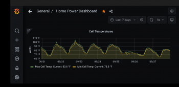
On the chiller. I ran it temporarily for about 90 minutes the other day (12:40-2:00). I didn't see much temperature change while running it. However it made a huge difference in the days temperature!

Now I just need to figure out how to get something like 100-300 watts of heat into the cells. It seems easy to use the same coolant. But, I haven't found a reasonable heater element that will fit into the reservoir or a heater matt that will stick to the reservoir.

Lots of small 10-20watt@12v mats. But, I'm worried about passing 4x the current through a 12v mat to get the heat output I think I need.

I suppose these small heater mats are $10, so no big loss of it doesn't work long term.

Screenshot_20210927-222257.png

Screenshot_20210927-222942.png
 
Here is a 1000 watt 120 volt water heater unit, it should be about 200 watts on 48 volts DC.
[https://www.amazon.com/Camco-02103-...lt+water+heater+element&qid=1632831997&sr=8-5

How about using a 240 volt electric hot water heater element, but just run it at 120 volts. 1/4 power. Here is a 1250 watt unit that should run about 300 watts at 120 volts.
 
Back
Top