diy solar

diy solar

Adding Schneider XW Pro

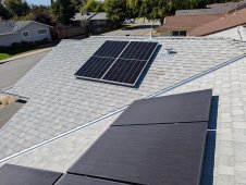
I got the two panels mounted on my small east facing roof section this morning.
I friend had planned to come over to help move those giant panels aground. I did the first along. It was mostly fine. The hardest part was picking up 65 lbs of panel that eas halfway up the ladder.
After doing the first, I knew I couldn't do the second.

Luckily the neighbor started lawn work and was able to help out.

Hopefully, tomorrow morning I can run the conduit through the attic. It got hot on the roof quickly this morning. 95 f is too hot for me to want to be on the roof or in the attic. For the first batch of panels in 2018, it was in the 60s and so much nicer.

The old 325 watt panels look filthy in this shot. Because they are...
PXL_20221007_190547831.jpg
 
Very nice. Looking forward to how it all performs together.
I pulled the trigger and have just 10 of the 100 watt panels coming to experiment with. I also ordered the Bouge 40 amp charge controller. I am going to just wire it up on the ground for a test like what Will does and see how it all performs charging my big battery bank. I'll post about it with pics in my thread. The panels and Charge controller should get here on Sunday.
 
I almost contacted you when I purchased these panels to see if I could cut down the drive time and pick some up for you. But, if you don't have a way to transport them it doesn't help and I was sure there were closer vendors for you.
Using many of the small panels should get you to the same spot. Just with lots of extra racking.

These things are huge. Nearly 4'*7' and 65 lbs. The smaller 60 cell panels were a piece of cake by comparison. Plus I had a second hand for those and a forklift to get the entire pallet at roof height.
 
65 pounds does not sound THAT heavy. But when it is also that big, it can become extremely awkward. And even the lightest breeze will make it into a sail. The fork lift is a nice touch. Renting one would blow my budget away.

If I bolt these into 4 panel groups, that would make it about 60 pounds each for 400 watts. So they are close. The extra frame material going through the middle makes this setup a little heavier per watt. The numbers are close enough though that it makes sense. I really hope these live up to their 21% efficiency spec. The total panel, frame and all comes out to 0.511 square meters. At 100 watts of output, that is just 195.64 watts per square meter.

My existing 300 watt Sil Fab panels are 1.6335 square meters each which puts them at 183.65 watts per square meter, and they were rated at 18.4% efficient. So that agrees with the watts per square meter calculation. By that, I would rate the NewPowa panels as 19.6% efficient. Still a tick better, but not 21%. The cells themselves may be up there though. The smaller active area to frame ratio does hurt a bit. My Sil Fab panels have the cells right up to the slim frame. The NewPowa has a bit of a gap and a thicker frame around a smaller active area. I knew going in that this was not going to be a major step in efficiency. It only does a hair better because the cells are a better design. When made into a 120 cell half cut panel, to be about same size as my Sil Fabs, I would expect a rating of nearly 375 watts. I am trying to estimate the actual cell size and space needed between them. The cells appear to be about 170 mm x 85 mm. I will try to get a better measure once the panels are here.
 
Yeah, 65 pounds wasn't the issue.
It's a combo of 65 pounds, the size of a sheet of plywood, and getting from 4' off the ground to 9' off the ground. It was literally just the one move from ladder to roof.
Luckily there really wasn't much wind yesterday, I don't know how well I could have moved around the 65 pound sails if it was windy.

Last time the forklift was free. It was actually forks in the bucket of my father's bobcat. Helping carrying 20 panels up a ladder was something he wanted to avoid. Since then, dad has moved out of the area, so no forklift this time.
 
I was up in San Fran again last week. I had thought about contacting you and stopping by, but I had no free time and had to get back. Maybe next time they send me up I'll have a few minutes.
 
I "finished" the wiring today! Right at about 5:00 pm and my array faces the sun rise. So, it charged at 21 watts for a couple minutes.

I'm going to try and figure out the communication and data logging tonight, so I can see how the system performs tomorrow.

I've got some clean up work todo, waiting on the correct battery side breaker, and I've got to order the map/placard and stickers.
 
This question is for those with XW6848 Pro inverters ...

I have two installations with the same firmware, Build Number 1.11.01bn49
In the local webpage for my Insight under the Battery Settings config part.
On unit has Bulk Termination Voltage
They both have Bulk Termination Time

I cannot figure out why one unit has the term. voltage setting and the other doesn't.
What does your Pro unit have ?
 
I still have not gotten around to updating my firmware, so mine is still on 1.03.00bn3

Under charge settings, it has
Bulk/Boost Voltage Set Point. This seems to be the important one that it charges up to while in Bulk charge mode.
Absorption Voltage Set Point. I have this set the same as above. Maybe you can let the voltage sag back while in Absorb mode?
Float Voltage Set Point. I also have this set the same, but I am in "No Float" so it does not mater

Then a few spaces down is "Bulk Termination Voltage" It only goes up to 54 volts, so I have it maxed out, no idea what it actually does. It discharges below this and charges up past it with no effect. Maybe it was used in some other version and is just a place holder now?

With my 14S Li NMC battery bank, I have those set to 56.98 volts. I know, that looks like an odd number, but it is 4.07 volts per cell.
My new DC charge controller is set to 57.2 volts for Boost Charge Voltage, and if it ever completes absorb (2 hours at 57.2 volts) it will then drop to Float at 56.8 volts. It has not hit it yet, fell short by just 0.2 volts today. The XW-Pro times out at 4 pm and goes to grid sell, but the DC charge controller kept pushing charge for another hour.
 
I have 17 cells of 280ah Eve -- two banks of these. Using the JKBMS one for each bank. No disconnect other than my control automation can send modbus commands to stop XW from charging and cause XW to stop discharge.
 
17 cells of LFP is a little unusual, but the setting in the XW-Pro should be able to work with it. What are you using for the max bulk charge voltage? I would think no more than 3.5 per cell, which works out to 59.5 volts. That is getting into the knee area, and the JK will need to balance well as a runner cell could hit over voltage very easily. But if you don't go above 3.35 per cell, you won't get into the knee, and your balance could drift, even if the voltages are really close. That is the one issue of LFP. The flat voltage curve is great for some things, but not so much for keeping the SOC balanced. I think 3.4 to 3.5 volts per cell is about as high as you can safely go. up there, a 9% change from 90% to 99% charged is only 0.025 volts per cell, and then just 1% more and the voltage goes twice as far 0.05 volts per cell. If only one cell is running, that 0.05 volt is basically invisible to the XW charger, but the BMS will see it.

On the low side, it is a little better, Just don't run down to the knee, and have the balancer stop trying to balance below 3.2 or 3.3 volts per cell. You can still run down to 2.8 per cell, but at 3 volts per cell, you are already down to just 9% remaining. 3 x 17 = 51 volt cut off. That is where I am with my 14S NMC. With a long series string like that, you really don't want your weakest cell to go off the knee on the low side. The weak cell could drop another 0.5 volts in just 9% more discharge. On a 280 amp hour cell, that is 25 amp hours. If all the cells top balance perfectly, then as long as the weakest cell is no more than 25 amp hours less capacity, you should be safe discharging to 3.00 volts per cell. A 25 amp hour weaker cell would hit 2.5 volts.
 
bulk boost 58.1
abs 58.6
float 57.5
bulk term 56.6
recharge volts 54

What should i be setting the times to ?
Absorb Time ?
Bulk Term Time ?

Am I correct to believe the SOC settings in Charger Settings are useless unless I use some S/E accepted battery system ?
 
17 cells of LFP is a little unusual, but the setting in the XW-Pro should be able to work with it. What are you using for the max bulk charge voltage? I would think no more than 3.5 per cell, which works out to 59.5 volts. That is getting into the knee area, and the JK will need to balance well as a runner cell could hit over voltage very easily. But if you don't go above 3.35 per cell, you won't get into the knee, and your balance could drift, even if the voltages are really close. That is the one issue of LFP. The flat voltage curve is great for some things, but not so much for keeping the SOC balanced. I think 3.4 to 3.5 volts per cell is about as high as you can safely go. up there, a 9% change from 90% to 99% charged is only 0.025 volts per cell, and then just 1% more and the voltage goes twice as far 0.05 volts per cell. If only one cell is running, that 0.05 volt is basically invisible to the XW charger, but the BMS will see it.

On the low side, it is a little better, Just don't run down to the knee, and have the balancer stop trying to balance below 3.2 or 3.3 volts per cell. You can still run down to 2.8 per cell, but at 3 volts per cell, you are already down to just 9% remaining. 3 x 17 = 51 volt cut off. That is where I am with my 14S NMC. With a long series string like that, you really don't want your weakest cell to go off the knee on the low side. The weak cell could drop another 0.5 volts in just 9% more discharge. On a 280 amp hour cell, that is 25 amp hours. If all the cells top balance perfectly, then as long as the weakest cell is no more than 25 amp hours less capacity, you should be safe discharging to 3.00 volts per cell. A 25 amp hour weaker cell would hit 2.5 volts.
fyi -- the balancer I have is a 24s, where i use 17 lines. All 17 cells in each bank were part of the same lot and date code.
 
Am I correct to believe the SOC settings in Charger Settings are useless unless I use some S/E accepted battery system ?
Yes, you need either the Schneider Battery Monitor or one of the few Batteries or BMS units that the Schneider system can communicate with. My main battery is also using a JK BMS, and I just use voltage control. But with Li NCM cells, the voltage changes a lot more and even fairly linear with state of charge, so voltage control works very well. With LFP cells, I think I would add the battery monitor to have a running state of charge that the system can see.

My JK BMS is also a 24 cell unit, 200 amp (350 peak) with 2 amp active balancing. It works great. I had one issue where my battery shut down, it was caused by a bad balance lead so it saw the cells on both sides as low and shut the system off. I fixed the connector, but those 2 cells still show a tiny bit higher wire resistance in the BMS ap.

The additional banks I added are just using dumb Daly BMSs. Turns out my cells are holding such good balance, that the active balancer never kicks on at all. So when I made 2 more strings, I figured the 0.060 amp passive balance would be fine. So far so good. I just did a manual cell voltage measurement and the new bank with the dumb BMS had all 14 cells within 0.005 volts from highest to lowest. The bank on the JK are within 0.003 volts.
 
Last edited:
So if you are ready I can send the hurricane your way -- I had the deal last month !!
 
If you want to stop the Insight local from logging you out, try TamperMonkey.

// ==UserScript==
// @name local Cgw
// @namespace http://tampermonkey.net/
// @version 0.1
// @description try to take over the world!
// @author You
// @match https://192.168.1.91/*
// @match http://192.168.1.92/*
// @icon https://www.google.com/s2/favicons?sz=64&domain=tampermonkey.net
// @Grant none
// ==/UserScript==

(function() {
'use strict';

Object.defineProperty(window, 'MAX_IDLE_TIME', {value:86400*365, writable: false});

alert("Timeout adjusted to " + window.MAX_IDLE_TIME);
})();
 
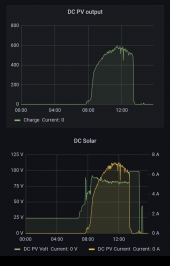
I finally set up some monitoring on the new DV coupled solar.

I'm surprised how quickly this set up ramps up in the morning.

It only took 30 minutes from 30 watts at 8:15 to 400 watts at 8:45. That 400 watts is 2/3rds of max production.

I'm still figuring out my charge settings between the XW and Mindnite. So, the Midnite kicks off suddenly at about 1:30 because the XW charged right past the Midnite charge settings.

But, at 2:30 I initiated a Rapid Shut Down as a test. It worked, PV voltage depleted quickly. But confusingly, the PV breaker tripped. This is a 15 amp 2 pole breaker.

And the system didn't seem to recover.
The Tigo RSD box should put out 0.6 volts when the RSD is active and should put the panels in parallel when operating. Currently I'm seeing 0.01 volts, not the correct 0.6 volts or 80-100 volts.

I've got a spare RSD module here, I could swap it out. I'm going to let it sit overnight in hopes that loss of sun will return some functionality to the system.
I'm not hopeful.

Screenshot_20221016-154453.png
 
That does seem odd. Tripping the RSD should not damage anything. The whole point of the RSD boxes is to "SAFELY" shut off the power at the panels. I thought the Tigo two panel RSD box connected the panels in series when it is switched on.

How hard is it to get up to your panels? Can you disconnect the MC-4 connectors and check the VOC and ISC at the panels? And if they look good, I would try bypassing the RSD boxes and make sure the charge controller comes back to life.

I do not know the spec of the "keep alive" signal, but if you have a scope, I would think you should see that on the line. Make sure it is sending the signal up to the boxes at the panels.

Do you have all 4 of your new panels up in place yet or is this still just the one pair? 7 amps at 80 volts comes out to about 560 watts, so I am guessing just 2 panels. When the RSD shut off, it must have sent some kind of inductive kick back out of the charge controller. My guess is the voltage spiked up enough to hurt the FET switch in the roof top RSD box(s). If the box shorted out, you may be able to measure the ISC current with a clamp meter going into the box from the panel.

I hope the Tigo RSD actually did survive, because I wanted to go with that as well, but this is not looking good. Keep us posted on what you find.
 
Yeah, I think the Tigo RSD box died.
I was going to climb up and swap out the module or do some testing, but the kids wanted to play. So, priorities.

I'm pretty sure the RSD box died.
The sun is down and I cut power to the charge controller and RSD transmitter for a couple minutes. The system still isn't acting normally.

Tripping the 15 amp PV breaker really confuses me.

I'm planning to call Midnite, Tigo, and AltE tech support tomorrow to see if they have any ideas before swapping in the replacement Tigo module.
 
I spoke with Tigo, Midnite, and AltE today. Everyone said about same thing ?‍♂️ just replace it.
So I threw up the second TS4 (it was not yet installed along with the second pair of panels) and the system is producing again.

I don't want to initiate another rapid shut down test for fear of the second and only TS4 dieing the same death and leaving this system inop waiting on Tigo's RMA process.
 
Back
Top