diy solar

diy solar

Adding Schneider XW Pro

Alright, so I did another off-grid test yesterday morning when the cells were low enough (3.6v) and PV was producing around 2000 watts.

I set the max charge current lower than normal to test the frequency shifting.

The Solar Edge inverter came back to life after the 5 minute time out, no prob.

The XW totally ignored the max charge current limit I had set and as the sun continued to raise in the sky, the battery was charging at roughly 8 amps over my max charge current with no signs of frequency shift. I had a DVOM hooked up. The frequency was moving from 59.99 to 60.00

I guess I will have to wait for the big battery to test the frequency shifting ability of the XW.


Good news on the low voltage cut off hysteresis.
I lowered recharge voltage to 49.8, left grid support at 50.5

They XW acted as I had hoped. As the battery hit 50.5 volts the current slowly decreased to hold the battery at 50.5 volts. Once it cycled off it never came back on.
 
@GXMnow
This was one idea I had, just have a controller take the unit off grid each night to run down the battery. Kind of a brute force kick start. The bad part is needing to operate a 60 amp contactor all the time.

@400bird
I believe you could use the onboard outputs of the Schneider to control this. I haven't looked into it, but that was Schneider's suggestion to me.

@pvdude
Great idea about using the Auxiliary Output relay!
Looks to have many configuration options, and might be a solution to operating
a contactor.

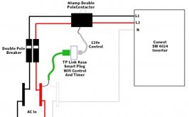
I control the AC in on my SW with a double pole 40amp contactor relay with 120v coil control. I ran a 120v plug off of one leg of the 240 split in put to the SW before the contactor and connected a TP Link Kasa plug. So now I can turn the input to the SW inverter on and off with my phone basically letting me control when I am off grid or in grid support mode. This also lets me set timers as two when I am on grid and off grid. Works like a champ. And is Alexia controlled too ;)

And it save you from having to run the contactor coil on all the time.
 
Last edited:
That is a decent idea. How well does your SW handle the shut off? Does any of your gear glitch? How do you charge your battery bank? Is it DC charge controller, or are you using any AC coupling?
 
Handles the shut off and on of the SW no problem. Does not glitch in and of itself. The SW has its own transfer switch inside, so once the power comes on from the contactor, the SW has to qualify the power first, so there is no glitching. I also use an Outback Autotransformer (see my sig) to balance the loads of the L1 and L2 of the SW. Works great.

When I power the contactor off, there might be a glitch depending on load, but not much.

Biggest issue I had was at first I tried to power the TP Link Kasa smart Plug 120v power from the L1 on the inverter side. That caused problems. My thought was, "then it will work even in a grid down situation". But instead, if the inverter was AC power in off, and the plug was getting power from the battery/inverter AC side, When I turned AC power from the grid on ... the contactor would go into "conniption fits" (yes that is the technical term - LoL). It would chatter like crazy. The contactor really did not like that at all. Other than that, works great.

I charge my 4x6v = 24v GC T105 batteries and run the loads off the house with a 2500+ watt array and a Midnite solar 150 charge controller (I have 9 x 285w 60 cell panels). My original battery bank of 4 L16 435s died (not because of mismanagement ~ but probably due to over charging for fear of sulfation). I replaced with GC batteries last spring until I could figure out what to do as 225ah is not enough. I was going to get 4 more GC batteries and connect them in parallel, but now I am awaiting delievery of 16 272ha LFP batteries to configure into an 8s2p bank with 2 overkill BMS units on them.
 
Last edited:
@GXMnow One question for you:

The SW is rated for 3200w continuous / 4000w for 30 min / 7000w surge 5 sec / 41amp peak

I assume that is 41amp total and not each leg as each leg is rated for 2700w

I Run a 1hp (or maybe its a 3/4 hp) 240v spit well pump . I have run it off the inverter off and on at different times for the past 3+ years. The SW starts the pump no problem at all. The 15 kitchen LED lights blink when it starts, but regular incandescent bulbs and other LED lights to not.

The pump runs at about 880watts and 2.6ish amps on each leg.

BUT ... Today I had for the first time and InRush amp meter. I tested the inrush, which is obviously for mere milliseconds, and I was getting 44.07 amps on L1 and 44.95 amps on L2. Like I say, after the motor start it runs at 2.7 and 2.3 amp respectively.

Clearly this is over the rated spec for the SW, But it seems to not mind doing it. The pump has always started perfectly and the only protest I see out of the system is the flicker in the kitchen LEDs. I had often attributed that to the huge voltage sage of the LA battery bank. Pump running I get down to 24v or less when I am at about 75% SOC.

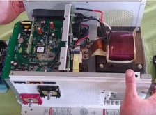
Question: Is that doing long term damage to the SW? Or if it is working, then it's fine? My understanding of the Schneider Conext SW series (not the old trace gear) is that the SW is actually a high frequency inverter, BUT it has a huge copper coil. The whole unit weighs in at 76 lbs.

I also am running 4/0 at 7 ft cable from batteries so the SW so there is not problem with wire size

The SW has NEVER shut down or threw and error code starting the pump. But am I doing Damage to the SW over time? If so I will not run it except in emergencies.
 
This is inside (not mine) the smaller SW2024. Pretty big coil in those units. I assume my SW4024 would be larger?

Inside the SW 4024.JPG
 
Ya, I need to get the part number of the particular AC relay that has started arcing.I think it would be fairly easy to remove the left side board and remove the solder and replace the worn out relay. Why they did not engage zero crossing I can fathom..
 
Mine is an XW-Pro, with a MUCH larger toroid transformer that is probably close to 70 pounds by itself. Schneider hardware is very robust. That starting surge from your well pump is certainly pushing the rated limits, but with how these are built, the only part I would be concerned about is the transfer relay. They do seem to be the one weak link. On the XW, they use a 3 pole relay, and jump all three together, for one leg, and another 3 pole relay, with all three jumped together for the other leg. But when it is in inverter mode, the current from the inverter to the outputs does not actually go through any of the relay contacts. The SW does appear to share the same design, just scaled down a bit. The overload protection on these inverters is pretty advanced. If it senses too much power, it will shut down. The fact that your start up surge is so short, it is probably not exceeding the short term limits. As you have seen, the voltage dips a bit on the surge, so the power is still within it's limit. If the dip goes too deep or lasts too long, it will shut down. These units can supply surges better than most inverters, even ones rated at more power.

If a relay in mine ever fails, I will solder in a socket. As for zero crossing, the relay they use is mechanical, and it takes time to build up the magnetic field, and start the contact moving. It really can't be timed precise enough to close exactly at zero cross. That is something they do in solid state relays. The turn on in mine never makes a spark. It starts inverting first, and does sync with the grid and closes the relay under very little voltage difference, making it nearly zero current. The shut off is when I see it spark a bit. There is nothing they can really do about that either. Especially in the case of a grid failure. For almost a full cycle, the inverter is trying to power the whole grid as it sees the bad grid and opens the relay. They claim in just 8 ms. It just does not seem quite that fast. 8 ms is under 1/2 of a cycle at 60 Hz.
 
Nice. Would you be at all interested in selling a couple of the bricks?
 
Sure. I'll probably hold onto both 8s modules. But, I don't know if I need them long term. I want to hold onto them just in case.
 
I would be very happy with 3 of the 10S bricks. But I forgot where you are. Shipping them can be a pain. If not too far, I could pick them up. You can PM me if you want to discuss price off the public forum.
 
I'm in the central valley near Lathrop. I could drive part way down and meet you in the middle.

If you've got no time frame I likely will be somewhere in the greater LA area in the next 2-4 months.

No idea on price, I'm still too excited to tear this thing apart. But, I must adult some. I've got at least 3 hours of work to do tomorrow morning...

Well, I thought I posted this reply last night. Surprisingly chrome or the forum saved my fully typed post even after closing the tab.
 
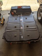
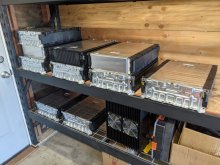
Got the case opened up today.
I've seen the horror stories of opening a Tesla or Nissan pack where the case is glued together. This was just bolts and a nice rubber gasket.

The pack label shows 64 kwh.
The labeling on each module brick is less than desirable.
I believe it is:
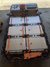
5.34kwh for the 8s module
6.68kwh for the 10s module

All the modules are heavy. Worse when assembled as two when pulling them from the pack!

PXL_20210409_230349653.jpgPXL_20210410_011524238.jpg
PXL_20210409_234057234.jpg
 
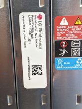
You made quick work of that. Nice stack on the shelves. Is that a 2011 Date code? Odd, I didn't think they were even working on the Bolt that far back. Maybe it is 2020 11th week? They look newer with the N2.2 Mine said Vista 2.0 and I think 2017 and 2018 date codes. The capacity is correct. I did the math backwards and that does work out to 60 amp hour cells, 10S 3P and 8S 3P. I am certainly not in any rush. Let me know when you are coming near Los Angeles, I am between the i5 and the 14 just a few miles north of where they meet. Mine also clearly said LiNMC, these show LiMM-C.F Not sure if that is a slightly different chemistry. Hmm. Ill have to look that up. I know they did make a change recently which was to improv the durability, but I just thought it was a process change, not a different chemistry. I have not found any web listing that talks about an LiMM chemistry. From everything I can find, even the current Bolt is still using NMC cells. I have no reason to think the charging specs would be different.
 
While I was searching for info on these battery modules, I found an update to the Chevy Bolt battery fire recall. It is only involving cars with N2.1 cells that were produced in the LG Chem plant in Ochang, Korea So your new pack being N2.2 is a good thing. That date code does seem to mean 11th week of 2020. My current packs are Vista 2.0, so before the bad cells in the recall. Guess we got lucky on both sides. I am still not charging above 90% though.
 
I'm glad to hear that. I didn't realize the recall only applied to N2.1 cells.

This thing is nearly fully charged. Sitting at 4.135-4.141 volts for the 30 cells I measured.

I thought the same thing about the date codes. It's got to be 11th week 2020, I don't see any other way to read it
 
I managed to get a picture of the sticker on my 8S battery module. I can't get to the 10S ones the way I have them bolted together, just no room.

It actually does say LiMM-C.F / LGE just like your sticker shows.
I could have sworn it said LiMNC oh well. All the text online says they are NMC cells.

The date code on this one is 1901 So yes, week 01 of 2019 makes sense.
My top line shows: Model Name: Vista 2.0 Cell Module Assembly
Next line Rated energy: 4.75 KWH this is the 8S again.
180 AH x 8 x 3.7 = 5.328 KWH in a perfect world. LG/Chevy seem to be rating them at 90%
 
I am a bit confused by LG/GM's capacity stickers.
The N2.0 and N2.1 packs are labeled 57 kwh and GM markets the car as a 60kwh. The N2.2 is labeled 64 kwh and GM is marketing it as a 66kwh pack?

Which cells are 60ah? Which are more or less. I haven't found a spec sheet on the N2.2 cells in my small amount of googling...

Anyways,
The copper for the bus bars arrived yesterday, so I was working towards splitting the 8s pack. Only to discover that I am out of small cut off discs... Oh well, try again tomorrow after a trip to the hardware store.

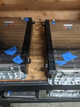
Also, I had assumed the 8x 10s packs were identical and just flipped for use down each side of the pack, I was incorrect. There are positive (left) and negative (right) packs down each side. Same for the 8s, but I need to measure and verify if the polarity for left and right matches the 10s packs.

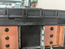
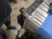
There is a small label in the molding on the pack. Just above the bus bar it says "3p10s Front LH"

In removal, I cracked one of the BMS connectors. So I decided to desolder that board to check it out. Nothing complex there. Just what looks like a SMD fuse per cell and traces over to the connector.
 

Attachments

  • PXL_20210415_234024390.jpg
    PXL_20210415_234024390.jpg
    127 KB · Views: 8
  • PXL_20210415_233746888.jpg
    PXL_20210415_233746888.jpg
    57.3 KB · Views: 8
  • PXL_20210415_233651773.jpg
    PXL_20210415_233651773.jpg
    59 KB · Views: 8
Back
Top